Transparent FDM 3D Prints are Clearly Stronger!
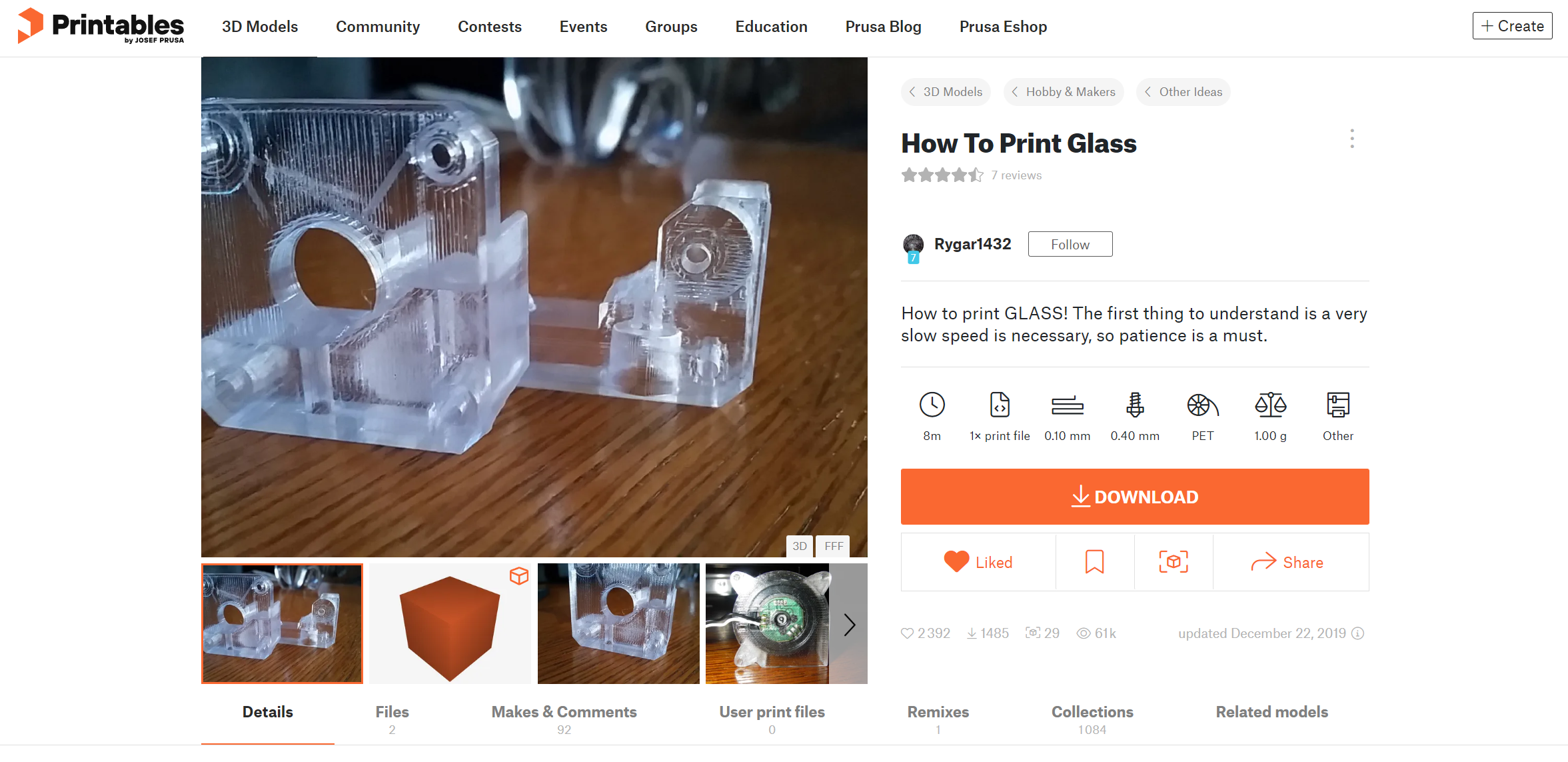
If you ever bought yourself a roll of clear 3D printing filament, you might have been quite disappointed that the parts you printed didn’t come out transparent and rather just looked more like a transparent whitish color. Though I recently stumbled over an article on printables.com where a user named Rygar1432 shared their settings with which they were able to print really nice looking, almost clear parts. The prints didn’t only look really nice, but I also asked myself what the strength of these parts was because they looked as if the layers perfectly bonded together, potentially eliminating the weak point of FDM 3D prints which is that they often tend to break within the layers. I don’t want to spoil the results - but I wasn’t disappointed!
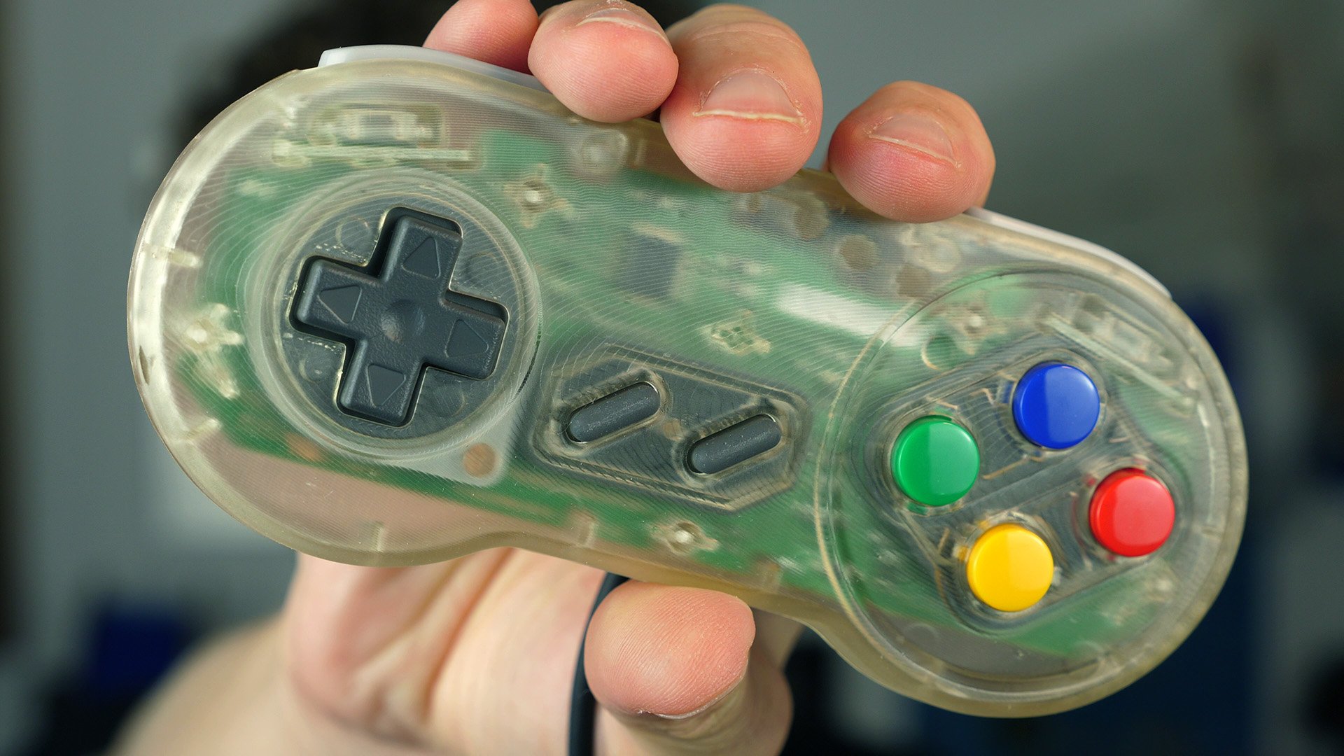
DIY transparent Super Nintendo Controller
So before we dive in here, let me quickly talk about something I’m sure many of you are already typing on your keyboards: Just use a resin printer if you need transparent parts! So yes, that’s theoretically an option but:
Not everyone has a resin printer and wants to deal with the mess and the smell.
Even if you use a resin printer, it’s kind of hard to get really transparent parts because they still usually turn out matte after the washing process due to the inherent voxel structure of the parts.
Even if you get clear resin parts by clear coating or resin coating them, they usually start yellowing quite quickly.
Then there is the selection of different materials for filament-based printing, which is just way bigger, and the properties, especially long term, are way better known.
and in the end, it’s just an interesting challenge to achieve transparent parts with an FDM printer and also see what effect this has on the mechanical properties.
So let’s save the challenge of printing real transparent resin parts for another video and if you have already started typing why don’t you tell me what applications you see for transparent FDM prints?
I’m not the first to do this because there is already a really old blog article from Colorfabb around as well as a nice video Tom did on that basis. There’ve also been a bunch of videos on how to print transparent parts using Polymakers Polysmooth material and then vaper smoothing them. However, those were mainly for vase mode parts. We’ll focus on real, thick-walled FDM parts today.
All of this came to my attention again, when a post by Rygar1432 on Printables circled around a couple of weeks ago with a set of recommended parameters that I tried out on a simple part and that worked really well on the first print. My first parts were in PCTG, but when I switched over to the more common PETG the parts still looked good but not as great anymore as on my first try.
This is why I thought it might be interesting to dive a little deeper into the parameters and what influence they have because Rygars recipe will not work for all of you. Filaments from different manufacturers will behave differently, and also your machine might react in another way. So take this as a guideline, what you could change to achieve transparent parts yourself.
Rygar recommends OVERTURE PETG, to which I put a link down in the description, and I’ve also read in different sources that some materials work better for transparent parts than others. I’ll say right away that I overall got even better results with freshly dried PCTG, but since PETG is way more common, all the investigations here will be done with PETG. In my case, I used a roll from dasFilament, which I purchased a while back for another project.
Modern slicers have hundreds of settings, and a significant portion of them will influence the clarity of our prints. Yet some are more significant than others and Rygar pointed them out in their post. I picked the flow multiplier, extrusion temperature, part cooling, and printing speed for my investigation but there are even more that might be relevant for you. There is layer height, perimeters, extrusion width, or outline overlap and probably a ton more. For each of my print jobs, I only varied one parameter at a time. I’m well aware that there are cross-influences and I’m certain I didn’t find the best parameter combination but this test series still showed me which parameter was more or less important.

Slicer Settings in CURA
I used PrusaSlicer for all of my tests and sliced a small test part I designed for this investigation at 0.12 mm layer height. Link in the description, by the way. I set the extrusion width for all features to 0.50 mm and only used one perimeter. And I think most importantly for the incredible results that Rygar got was setting the Infill to Aligned Rectilinear at a 0° angle with 0 top and bottom surfaces. This means that the infill is not printed in a criss-cross pattern but with all infill lines parallel. This tremendously helped to get rid of the last remaining pores. I also limited speeds to only 15 mm/s and turned cooling off.

Aligned Rectilinear Infill
The first one and probably also the most important parameter I played around with was the extrusion multiplier which I varied between 91 and 105%. The parts got clearer the higher I set the extrusion multiplier, and I already got really great-looking parts at a bit above 100% flow, where the material was able to flow into all the remaining cracks and voids. The parts didn’t get less clear at higher extrusion amounts, but you’ll get swollen-up parts due to over-extrusion and really rough top surfaces. Due to the lack of cooling, overhangs and holes didn’t look particularly great.
Off the bed, the parts might not look as nice as in some pictures. I use gluestick on my bed and that leaves a matte bottom layer, but if you polish that up or even only add a drop of water or oil, you can really get an idea of how the inside of a part looks and how clear you can get the parts. The side walls, due to their roughness still are not perfectly transparent, but even lower layer heights might help you in that regard.
Next, I tested the extrusion temperature. The dasFilament PETG prints quite cold, and I tried 215 °C to 250 °C in 5 K increments. I only got some weird printing problems at the lowest temperatures, but all the others looked fairly similar at first glance. However, a closer look revealed that I got some milkiness at higher temperatures due to microbubbles that formed in the material, probably due to moisture. And this is something I noticed over my whole test campaign. When I started the PETG was freshly out of the box, and the PCTG just came out of the dryer. The first print results were the most consistent and the easiest to achieve. The longer the material set around outside, the harder it was for me to get nice results. So maybe remember this point and if you’re serious about clear printing, then dry your material. Overall, 220 °C looked the best for my material and keep in mind that besides the bubbling we saw, materials will even degenerate if they are too hot for too long which I’ve also seen on some parts due to their brownish hue.

Micro Bubbles in the Material
Let’s, at this point, also talk about why regular prints with transparent material are not as transparent as glass for example. So light refracts when it moves from one medium to another and bends depending on the materials and inclination angle. In our case, the two materials are air and PETG. A regular print is not solid material, so the light passes through dozens of these interfaces, where it refracts, diffracts, and reflects, which is completely irregular and, therefore, parts rather appear shining white than really translucent. Even if we print with 100% infill, there are still a ton of voids in our parts where refraction happens. These are gaps between the extrusions but also the interfaces between individual extrusions where the polymer is not properly melted together, which also makes those parts appear milky. So if we want to print transparent parts, they need to be really 100% filled, and the extrusions need to melt together perfectly.
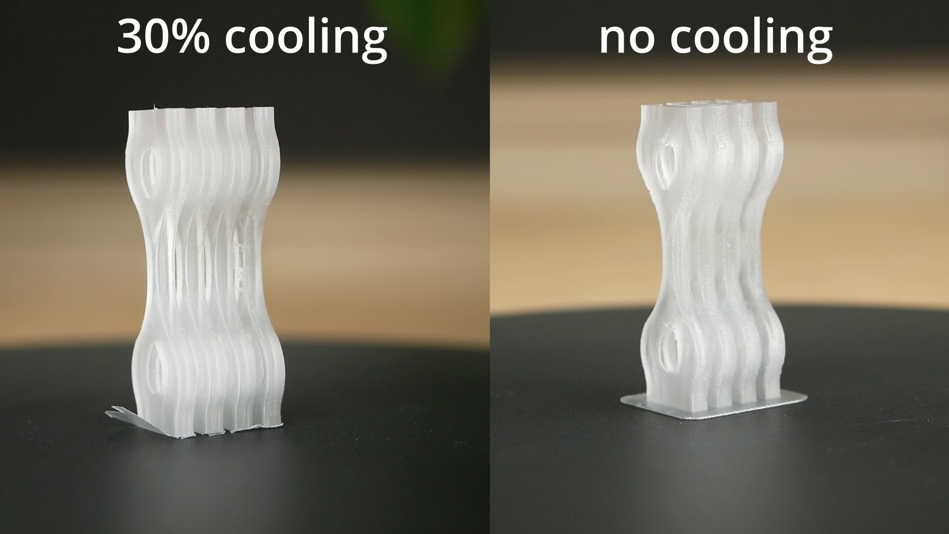
A parameter that could affect the bonding of layers might be part cooling, and Rygar warned about that. I tried it myself and printed parts at 0, 20, 50 and 100% cooling and indeed, the parts without any cooling were the clearest, though interestingly, the parts where I turned cooling on only turned a bit milky yet showed a way better part quality at bridges and overhangs. So if the clarity of your parts is not your primary goal but you want only really strong prints, then maybe turn a bit of cooling on, especially since I’ve seen a very interesting impact on static strength as we’ll see in a bit!
Finally, I tested print speed because maybe something I didn’t make that clear yet, printing these transparent parts is horribly slow. The very thin layers and the 100% infill are part of that problem, but the low recommended printing speed makes them even take longer. The small test samples took 50 minutes each to print, a 3DBenchy takes 5.5 h and my MiniMe figurine would take over 16 h to print, which is kind of ridiculous. In my test, I tried speeds from 5 all the way to 60 mm/s and the results were really interesting. 5 and 10 mm/s were not as clear as I thought due to microbubbles that formed in the material because the filament remained too long in the meltzone. 15 mm/s looked the best, but also, the higher speeds didn’t look that much worse, so there is definitely some speed potential left.
Now that we’ve seen that printing clear admittedly is not fast but not super hard to do if you know some impacting factors, let’s look at what really sparked my interest. How strong are these transparent prints, especially between the layers? And just to make things clear, even though I did all of these tests with natural clear material, these printing parameters can be easily transferred to dyed materials with probably the same effects on strength. To test how strong the transparent parameter really is, I printed tensile samples in horizontal and vertical orientation as well as impact specimens to get an idea about the toughness. My transparent parts were printed at 230 °C nozzle, 0.12 mm layers, 102% flow and no fan. The reference parts I printed used standard PrusaSlicer parameters at 100% infill. I printed sets of my simple samples, but since I wanted to get an idea of how everything also behaved on bigger parts, so I also printed standard ISO dogbones and bigger layer adhesion samples. The parts came out okay but definitly with some printing problems due to the high extrusion amount and lack of cooling. Yet, you could clearly see the difference between the milky-looking parts with stock parameters and the clear-looking transparent parameter parts. Usually, part cooling decreases layer adhesion, but since the lack of it, especially at the 100% infill, also caused slight printing problems, I also printed a set of samples at 30% cooling, which were still transparent but quality-wise looked way nicer.
Standing Tensile Samples
I tested the samples one after the other on my DIY universal test machine and measured each of the test sections to take the real dimensions into consideration. Let’s start with the reference that I printed with regular parameters. The horizontal specimens failed at 52 MPa on average, whereas the ones printed standing failed at only 34 MPa. This is less, but a layer adhesion strength of 65% is still remarkable for FDM prints. So let’s get to the parts that I printed with the “transparent parameter”. The horizontal specimens were already stronger, with 59 MPa on average, probably because the optimized parameter was able to print a fully dense part, so there was more material to take the load. They also significantly yielded whereas the parts with the standard parameter simply snapped. The layer adhesion samples impressed even without looking at the numbers because they significantly yielded before breaking, which is something you usually don’t see with these samples. With 44 MPa failure load on average, they were not only 30% stronger than parts printed with a normal parameter, they also reached 75% layer adhesion which is impressive. What’s even more impressive is that the samples that I printed with the transparent parameter but 30% cooling even outperformed these samples, probably due to fewer printing issues, and reached over 80% layer adhesion. And I need to be even more enthusiastic because the bigger samples performed even better. The ISO dogbones failed at 59 MPa, just like the small samples, but the bigger and round layer adhesion samples reached 54 MPa, which is 93% layer adhesion and is something I would not have expected and blows me away!
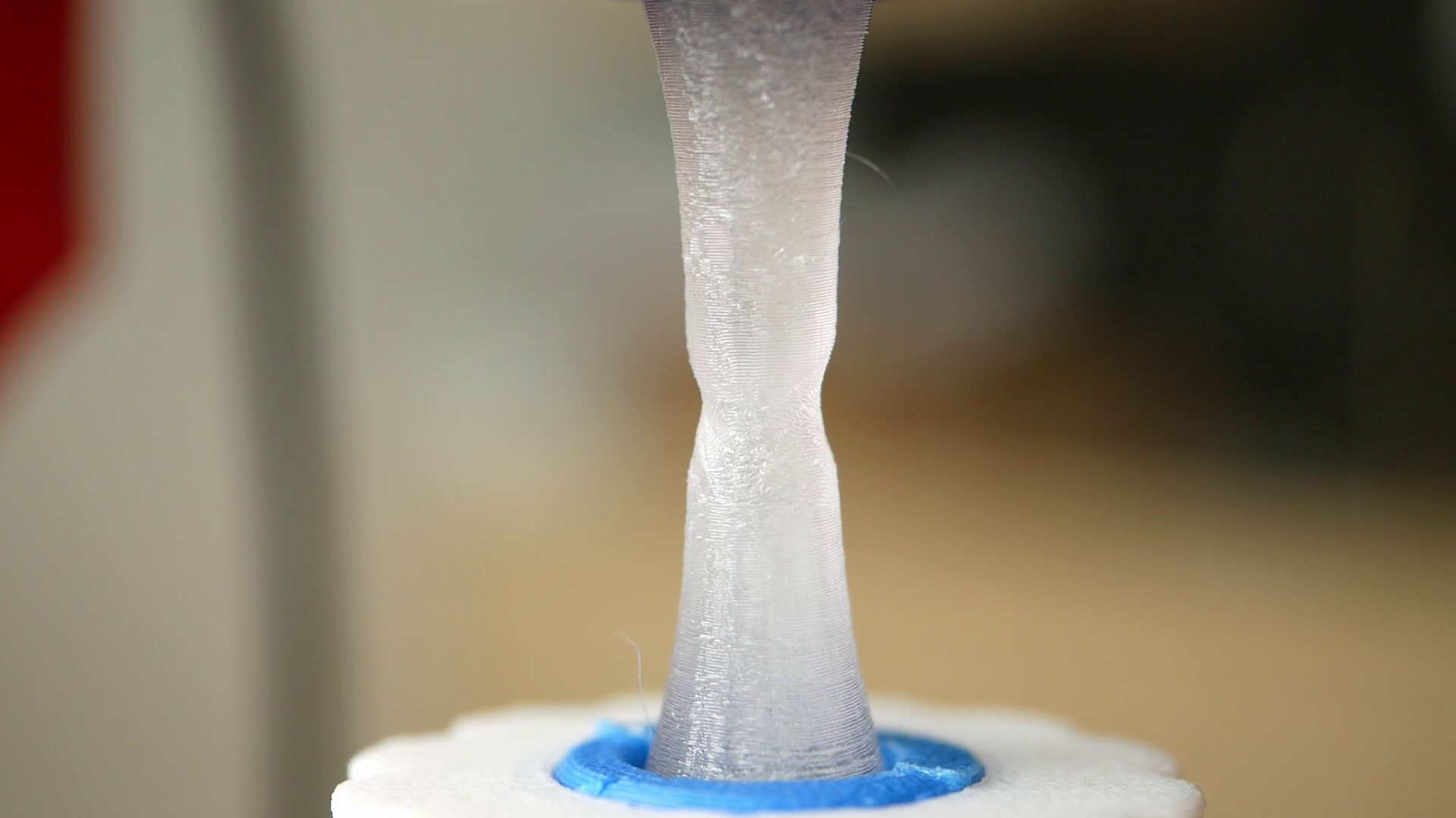
Necking of a layer adhesion sample
This shows the potential of this transparent parameter because if you’re able to set it up for your material and have parts that can be printed with it, the strength of these parts will be almost independent of the printing orientation, which is basically the holy grail of 3D printing!
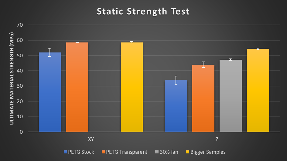
Axial Strength Test Results
For completeness, let’s also talk about impact performance, where I smash a hammer with known energy into parts and measure how much energy is absorbed during the impact. The more energy it takes to break the part, the tougher it is. On the horizontal samples, the transparent parameter outperformed a regular part quite a bit but also showed significant scatter. On the ones printed standing, the transparent parts were also stronger but didn’t reach the performance of the ones printed on the bed. I think that this is simply one of the limitations of the process because even though layers bond very well together, the majoriy of the polymer chains will remain oriented in the print plane, which decreases toughness and ductility perpendicular to it. That’s a bit of a bummer but something that can be dealt with.

Impact Strength
So there we have it! Prints with this transparent parameter are not only really nice to look at, but they are significantly stronger than parts printed with regular parameters, and we were able to reach almost perfect layer adhesion. If you want to tackle that yourself, use my or Rygars parameters as a start, and you’ll be able to get good results very soon. The questions that remain for me are if this process can be adapted for other materials and how easy it is to find the sweet spot for filaments that are not transparent because this was our perfect indicator for that test. I also want to see how we can speed up the process because, for the moment, you can only seriously apply that to small parts! Unfortunately, I think that the low speed is one of the key factors why this method works so well and why the layer bonding is so good. I tested thin layers as well as overextrusion in the past and never got these great results. Though this means that there is still a ton of research neccessary to dial this in for other materials and find that sweetspot parameter, that’s very strong but still fast!
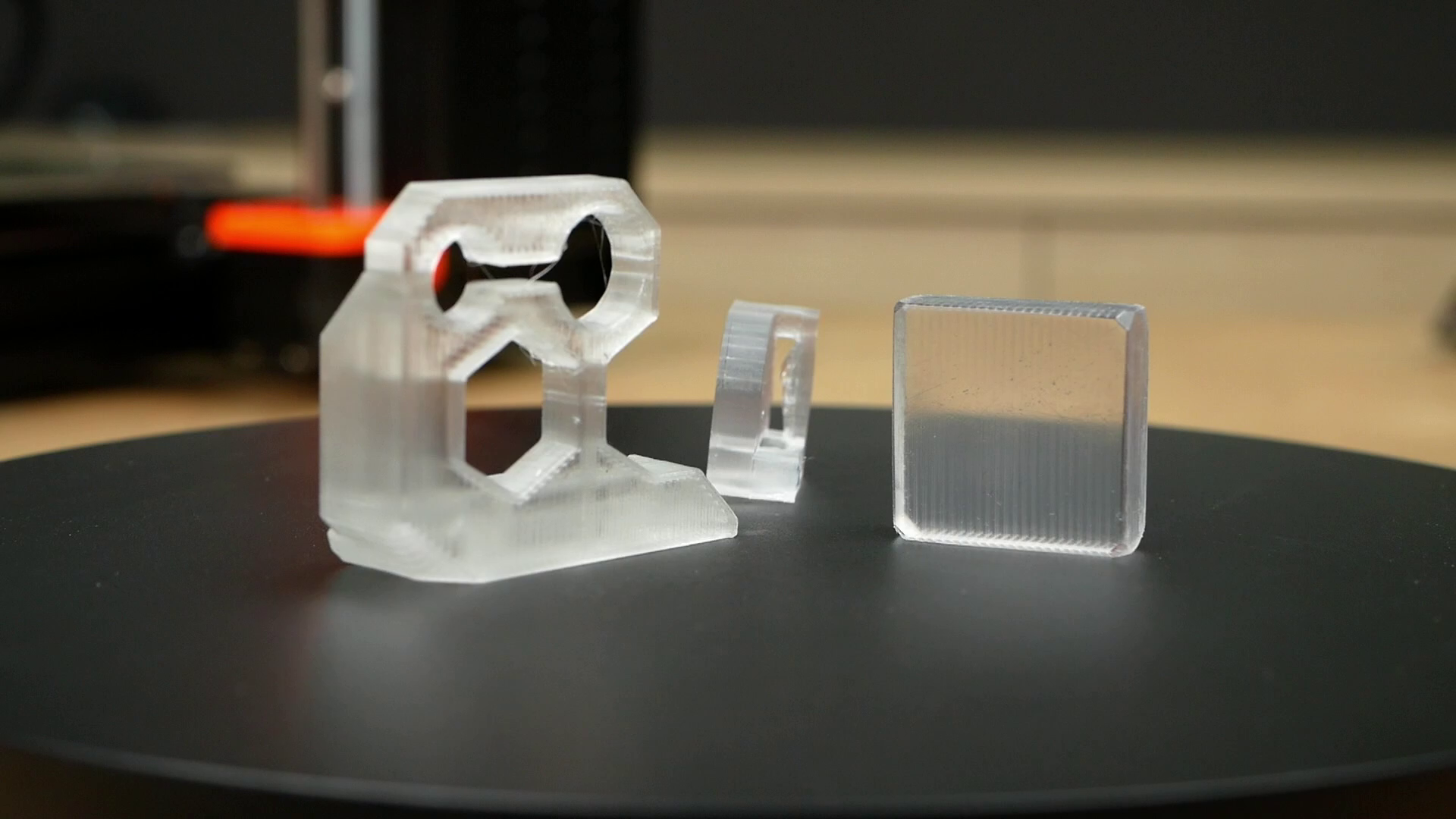
Transparent Parts
If you want to use this for your designs, make sure they are suitable because the results on very complex geometrys at the moment are not great. Regardless, I think this is again another small yet significant way forward for stronger parts and also if gas or fluid-tightness is something that you’re after. And if it’s not strength, then just think about complex light pipes or even optics. But what are your thoughts? Please let me know down in the comments!
📚 Further information
Tom's video on clear 3D prints: https://youtu.be/QkfQri2B0PY
T3DPG video on transparent PolySmooth prints: https://youtu.be/92C10-n21Po
Colorfabb article: https://learn.colorfabb.com/lets-make-something-clear/
dasFilament PETG: https://www.dasfilament.de/filament-spulen/petg-1-75-mm/136/petg-filament-1-75-mm-natur?c=21