Building a VORON 2.4 R2 in 2022 (LDO Kit)
If you’re only the slightest bit interested in 3D printing I’m sure you’ve heard the name VORON printer over the last two years because those machines combine everything an enthusiast 3D printer user want’s to have on their machine! CoreXY kinematics, linear rails on all axis, Klipper with input shaping for super fast, yet accurate printing, a beefy milled aluminum bed for perfect first layers, professional electronics, drag chains, lights, enclosure, air filter and so much more! Yet, you can’t buy a Voron off the shelf. In this video I’ll talk about how owning a Voron today is way easier than it used to be. Is the hype deserved and how relevant a Voron still is in the age of highspeed printers like the Bambulab X1, that you can buy ready-to print, off the shelf for less than a Voron 2.4 costs.
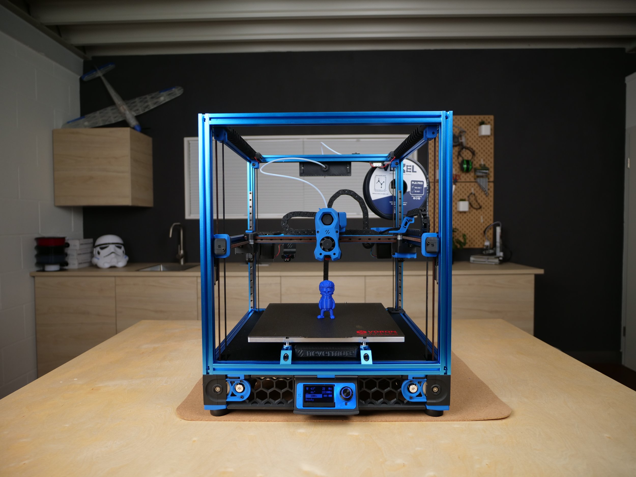
My VORON 2.4
So what is VORON in the first place? VORON is an open-source project around a group of very talented engineers, that try designing non-compromise 3D printers since 2015. Over the years a very active community formed around the project that uses the machines, provides feedback and created a ton of mods. There are several Voron designs available, from the tiny, yet capable VORON 0 that I built last year, to the latest large print volume Voron 2.4R2, that I built for this article.
Yes, I had to build one because Voron is not a company selling their printers, it’s a project that designs them and provides sourcing guides to buy the proper components to build them. And this is the reason together with component prices from $700 to over $1500, that there aren’t that many around. Building a Voron requires time and skill, in my case around 30h of assembly and wiring, knowledge because you still need to decide on some parts yourself like the hotend and dedication because even though with the base configuration you get a working machine, tuning it to your needs is left up to you.
Get an LDO Voron 2.4R2 Kit
Matterhackers (US): https://geni.us/AtBg1QM
3DJake (EU): https://geni.us/vt1m
Worldwide Resellers: https://docs.ldomotors.com/voron/LDO_Voron_Distributors
Get an LDO Voron 0.1 Kit
Matterhackers (US): https://geni.us/AKABg
3DJake (EU+): https://geni.us/fNO0q
But how do you build one in the first place? In the past you had to, and Voron even recommended to source all of the parts individually by yourself, yet over the last two years, more and more parts kits got available, which makes building a Voron today way easier than it used to be. This limits the base customizability but honestly I would have never built one myself, if I had to order everything separately! I got and built the Voron 2.4r2 kit from LDO, which currently sells for around $1350 depending on where you live and order from. All I’ve heard is that this kit is probably one of the best out in the wild for that price and LDO kindly provided for this video. This kit is fortunately available from many resellers around the world, so you don’t have to order from China and I put some links in the description. Just as a disclaimer, LDO sent me the kit free of charge, yet all the thoughts in here are my own and they even explicitly asked me to be completely open with feedback - positive and negative and this is something I highly honor. LDO didn’t just throw random parts together but include parts that work and fit the budget using the feedback from the Voron team. There are other Voron kit vendors around and I highly recommend to check the Voron Discord to find out if they are trustworthy or not. Already when buying the LDO kit you learn a bit about one Voron philosophy which is that you don’t build THE Voron, you build YOUR Voron. So with the LDO kit you can choose between three different sizes, which is 250, 300 and 350 mm squared build area, and a wide variety of frame colors to adjust the color scheme to what you like. The smaller sizes are at first cheaper but also more sturdy for higher speeds and more energy efficient, yet of course, smaller. I went for the middle ground and chose the 300 mm model. The other thing you’ll also need to decide yourself with the LDO kit, is which hotend you’d like to use, because it doesn’t come with one. Voron provides mounts for Phaetus, E3D and Slice Engineering hotends. I went with E3Ds REVO Voron hotend, because I had one and changing nozzles on it is so convenient and I also thought that the Voron will be a perfect platform for test the upcoming abrasion-resistant ObXidian nozzle. The other thing my kit didn’t include because they are currently very hard to source is a Raspberry Pi which runs the web interface and the Klipper firmware. Either you still have one, buy a new one for scalper prices or what I actually would recommend is buying a used Raspberry Pi 3 on eBay, which is totaly sufficient if you use the lightweight Klipper interface Mainsail or Fluidd. Yet, the LDO kit comes with some extra parts and mods, like a ton of handy adapter PCBs, that sometimes require to slightly deviate from the standard manual but LDO documented everything on their website.

LDO Voron 2.4 Kit
Besides the hardware and electronic components, you’ll also need the printed parts which are usually not part of the kit. I could talk for hours about the awesome design of the these parts. Not only do they all follow a common design language but they are all designed FOR additive manufacturing. This means, that none of the parts needs supports and if some features do, supports are integrated in the stls and easily removable. They apply all the tricks to get even complex bridges and holes to print which just warms my heart, so kudos to the Voron team! These should be printed ABS or other materials that are capable of handling the elevated temperatures in the chamber and at the stepper motors. Don’t experiment as I did on my Voron 0, where all the carbon fiber Nylon parts creeped and deformed after no time, and stick to Voron’s recommendations! I used ESUN ABS+ for all of the parts. Vorons are usually printed in a two color scheme. As mentioned before, you chose a frame color and then print the parts in a dominant color and the accent color. Suitable to my channel colors I chose the blue frame with blue accent parts and a black base color. To print all the parts you’ll need two rolls of the base color and one roll of the accent color. The full set of parts took me over 200h to print on my Prusa Mk3. If you don’t have a printer at all or just one that’s not capable of printing ABS then you can also use the Print it Forward program to purchase a full set of parts at a very reasonable price, probably also printed on a Voron, so fully follows the spirit of RepRap.
3D printed parts
Depending on your skill level and depending on which parts or kit you use, building a Voron 2.4 will take you around 20 to 40 h, from start till the first print. The Voron team prepared a 300 page manual through which you are guided step-by-step. It explains the steps very well with illustrations and short texts. For me, it almost perfectly was on the level of depth I require and it didn’t go as deep, as for example a Prusa manual which documents each individual screw you have to tighten and how many gummi bears to eat while you do that. Don’t get me wrong, the Prusa manuals makes building one of their machines very approachable, but if you build a Voron you should have some prior knowledge on how a 3D printer works, so condensing the manual down is totally okay! Oh and talking about manual. You’ll basically have 5 manuals. The 2.4 manual, the optional Stealthburner toolhead manual, LDOs additional wiring guide, LDOs neccessary and optional mod guide and Vorons software installation guide. So familiarize yourself with them before you start to not miss anything! As I almost did… I also recommend downloading the CAD model of the printer if something isn’t completely clear and join the Discord if you have any questions during the assembly. Oh and I also only realized after talking to the Voron team that the manual is for the 250 mm Voron2.4, so sometimes the number of t-nuts or proportions didn’t match my machine.

Motor assemblies
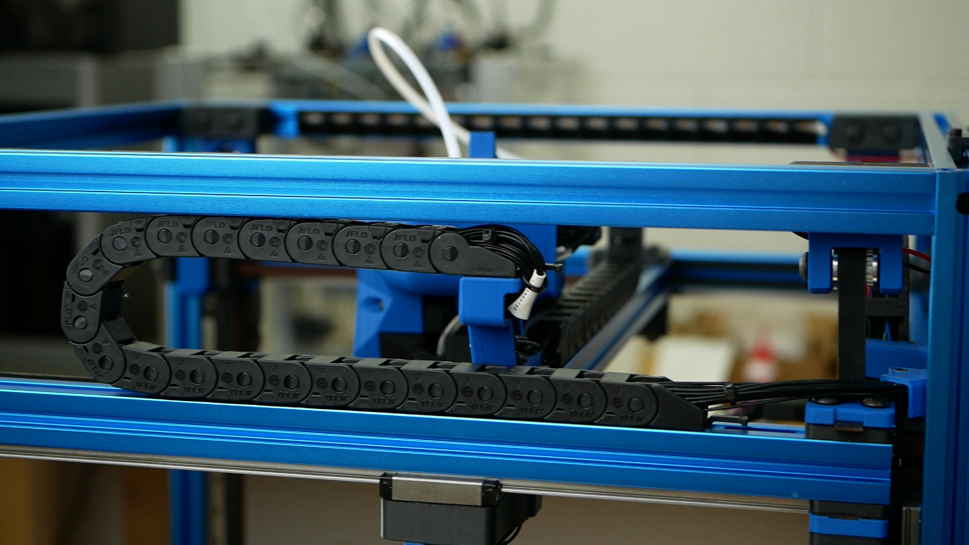
The build itself was super pleasant. All the parts in my LDO kit were clearly labeled and sorted by category; extrusions were cleanly cut, drilled, and tapped. It was also nice to see that LDO even included matte back acrylic sheets with chamfers because they are way less prone to fingerprints and dirt than glossy ones. The kit of course came with the suitable LDO stepper motors with Gates belts. The linear slides were not by HIWIN, but LDO sourced and branded their own set. They looked and felt very usable from all I can tell after cleaning them from their shipping gunk and re-greasing them, which is by the way clearly mentioned in the manual. The cable chains are also not by IGUS, yet you can open them which makes wiring way easier. I had the feeling that LDO didn’t choose the highest quality components to keep the price reasonable but still went with good mid-tier options that will suit the needs of most. The kit came with the parts for the Clockwork 1 extruder including original Bondtech gears, though if you want to go for the latest Clockwork 2 extruder, you only need to purchase a new stepper motor. LDO told me, that they are planing to include the new stepper, yet the kits that are at the resellers currently, still come with the old one.

Cleaning the linear rails
To be super honest, I didn’t film a ton of the assembly process because I wanted to enjoy it and really did that. If you’re interested in a full video build series of the LDO kit, then check out Nero3D. His videos are also a great resource, if you’re stuck somewhere! Most of the parts came together perfectly. Some of the assemblies were just beautiful to look at, and I had a ton of fun during the whole process! I didn’t have to rework any print and was also super happy to see that they used brass threaded inserts wherever they made sense. cnckitchen.store by the way. First, I assembled the frame and installed the z-axis rails and the super heavy aluminum bed, with the pre-installed heater matte and magnetic sheet. Then I put together the XY-gantry and installed it to the frame. Then I came to the toolhead where I made several choices. First, I didn’t go for the standard inductive probe, that often suffers temperature drift problem but went with the Klicky probe for which the parts are included in the LDO kit. This is a microswitch probe, that’s magnetically fixed to the printhead during probing and then parked in the back of the printer. Then I built the Clockwork 1 extruder and opted for the new Stealthburner toolhead for my Revo Voron. Since the Revo is currently limited to around 15 mm³/s extrusion rate you should also check out the other compatible high flow hotends, if you primarily want to print with larger nozzles.
The whole mechanical assembly was just like Lego for adults! Yet, I would still only recommend the build to someone who enjoys that task, because not only do you need to spend a good 30 h on that process but you also need a bit of engineering thinking to understand the manual and get everything square and running smoothly. And once you’re finished with the mechanical assembly you’ll need to wire everything. In the past this was one of the most tedious tasks, because running all the wires separately and crimping connectors was quite a pain! The LDO kit also makes this quite easy, because it includes a pre-made wiring harness with all of the suitable connectors already crimped, saving you a ton of time, mistakes and headaches during that process. It still requires a bit of basic understanding of electronics and you also will need to do a bit of wiring on the mains side which can be potentially very dangerous. So if you don’t feel comfortable doing this, either don’t build a Voron at all, or make sure you have someone, who can assist you. Overall routing the wires was pretty simple and the toolhead PCB, as well as DIN rails in the electronic compartment together with cable channels made the wiring very clean. The heated bed runs on mains, is properly grounded and thermally fused and uses an SSR for switching. The power supply is from Meanwell and the mainboard is an BigTreeTech Octopus with TMC2209 drivers. The only thing I can complain about is that my power supply didn’t have any protection over the mains terminals, but as soon as the lower cover is installed shouldn’t be a problem anymore.
Electronics
I didn’t install the side panels, doors, and top cover yet, since my first plan was to print a significant amount of PLA, where any enclosure will be bad for cooling. And remember what I said in the beginning? I’m building my Voron and not the Voron! Yet as soon as I’ll start testing the ObXidian nozzle from E3D with different carbon fiber Nylons, I’ll install them. I already put together the Nevermore Activated Charcoal filter for which the necessary fan is also included in the kit.

Nevermore Activated Charcoal Filter under the bed
From here on, it was simply following the guide on flashing the Klipper interface Mainsail onto an SD card, installing it into the Raspberry Pi, and hoping for the best when turning on the printer for the first time. Mine didn’t lose any magic smoke, by the way. Then I compiled the Klipper firmware, put that onto an SD card and installed that in the mainboard. This sounds scarier and more complicated than it is, because there are easy-to-follow instructions on the Voron website and if you’re still getting stuck there are some great videos by Teching Tech to check out! Finally I used the config file from the LDO website, ran PID tuning for the bed plus the hotend and was basically ready for the first test print! Since this is a fully open system, you can use any slicer that you like but since I create most of my GCode in Prusaslicer I went with this piece of software that has already profiles for the Voron included. I still had to do some manual configuration to get the Klicky probe and mesh bed leveling working but then it was ready to go. I by the way posted my config in my website article, if you want to take a look at it. A quick first layer test showed very promising results and the measured unevenness of the bed was only +-0.1 mm which is probably more a result of a deformed gantry than a warped bed.
My current, yet not super optimized printer.cfg:
# This file contains pin mappings for the LDO Kit using BigTreeTech Octopus V1 as the main controller.
# To use this config, the firmware should be compiled for the STM32F446 with a "32KiB bootloader"
# Enable "extra low-level configuration options" and select the "12MHz crystal" as clock reference

# after running "make", copy the generated "klipper/out/klipper.bin" file to a
# file named "firmware.bin" on an SD card and then restart the Octopus with that SD card.

# See docs/Config_Reference.md for a description of parameters.

## Voron Design VORON2 250/300/350mm BigTreeTech Octopus V1 TMC2209 UART config

## *** THINGS TO CHANGE/CHECK: ***
## MCU paths                            [mcu] section
## Thermistor types                     [extruder] and [heater_bed] sections - See 'sensor types' list at end of file
## Z Endstop Switch location            [safe_z_home] section
## Homing end position                  [gcode_macro G32] section
## Z Endstop Switch  offset for Z0      [stepper_z] section
## Probe points                         [quad_gantry_level] section
## Min & Max gantry corner postions     [quad_gantry_level] section
## PID tune                             [extruder] and [heater_bed] sections
## Thermistor types                     [extruder] and [heater_bed] sections
## Probe pin                            [probe] section
## Fine tune E steps                    [extruder] section

[mcu]
##  Obtain definition by "ls -l /dev/serial/by-id/" then unplug to verify
##--------------------------------------------------------------------
serial: /dev/serial/by-id/usb-Klipper_stm32f446xx_0A001100095053424E363420-if00
restart_method: command
##--------------------------------------------------------------------

[printer]
kinematics: corexy
max_velocity: 500
max_accel: 6000
max_z_velocity: 40          #Max 15 for 12V TMC Drivers, can increase for 24V
max_z_accel: 350
square_corner_velocity: 7.0

[include mainsail.cfg]

#####################################################################
#   X/Y Stepper Settings
#####################################################################

##  B Stepper - Left
##  Connected to MOTOR0
##  Endstop connected to DIAG0
[stepper_x]
step_pin: PF13
dir_pin: PF12
enable_pin: !PF14
rotation_distance: 40
microsteps: 32
full_steps_per_rotation:400  #set to 200 for 1.8 degree stepper
endstop_pin: PG6
position_min: 0
##--------------------------------------------------------------------

##  Uncomment below for 250mm build
#position_endstop: 250
#position_max: 250

#  Uncomment for 300mm build
position_endstop: 300
position_max: 300

##  Uncomment for 350mm build
#position_endstop: 350
#position_max: 350

##--------------------------------------------------------------------
homing_speed: 100   #Max 100
homing_retract_dist: 3
homing_positive_dir: true

##  Make sure to update below for your relevant driver (2208 or 2209)
[tmc2209 stepper_x]
uart_pin: PC4
interpolate: false
run_current: 0.8
sense_resistor: 0.110
stealthchop_threshold: 0

##  A Stepper - Right
##  Connected to MOTOR1
##  Endstop connected to DIAG1
[stepper_y]
step_pin: PG0
dir_pin: PG1
enable_pin: !PF15
rotation_distance: 40
microsteps: 32
full_steps_per_rotation:400  #set to 200 for 1.8 degree stepper
endstop_pin: PG9
position_min: 0
##--------------------------------------------------------------------

##  Uncomment for 250mm build
#position_endstop: 250
#position_max: 250

#  Uncomment for 300mm build
position_endstop: 300
position_max: 300

##  Uncomment for 350mm build
#position_endstop: 350
#position_max: 350

##--------------------------------------------------------------------
homing_speed: 100  #Max 100
homing_retract_dist: 3
homing_positive_dir: true

##  Make sure to update below for your relevant driver (2208 or 2209)
[tmc2209 stepper_y]
uart_pin: PD11
interpolate: false
run_current: 0.8
sense_resistor: 0.110
stealthchop_threshold: 0

#####################################################################
#   Z Stepper Settings
#####################################################################

## Z0 Stepper - Front Left
##  Connected to MOTOR2_1
##  Endstop connected to DIAG_2
[stepper_z]
step_pin: PF11
dir_pin: PG3
enable_pin: !PG5
rotation_distance: 40
gear_ratio: 80:16
microsteps: 32
endstop_pin: PG10
##  Z-position of nozzle (in mm) to z-endstop trigger point relative to print surface (Z0)
##  (+) value = endstop above Z0, (-) value = endstop below
##  Increasing position_endstop brings nozzle closer to the bed
##  After you run Z_ENDSTOP_CALIBRATE, position_endstop will be stored at the very end of your config
position_endstop: 2.35
##--------------------------------------------------------------------

##  Uncomment below for 250mm build
#position_max: 210

#  Uncomment below for 300mm build
position_max: 270

##  Uncomment below for 350mm build
#position_max: 310

##--------------------------------------------------------------------
position_min: -5
homing_speed: 8
second_homing_speed: 3
homing_retract_dist: 3

##  Make sure to update below for your relevant driver (2208 or 2209)
[tmc2209 stepper_z]
uart_pin: PC6
interpolate: false
run_current: 0.8
sense_resistor: 0.110
stealthchop_threshold: 999999

##  Z1 Stepper - Rear Left
##  Connected to MOTOR3
[stepper_z1]
step_pin: PG4
dir_pin: !PC1
enable_pin: !PA0
rotation_distance: 40
gear_ratio: 80:16
microsteps: 32

##  Make sure to update below for your relevant driver (2208 or 2209)
[tmc2209 stepper_z1]
uart_pin: PC7
interpolate: false
run_current: 0.8
sense_resistor: 0.110
stealthchop_threshold: 999999

##  Z2 Stepper - Rear Right
##  Connected to MOTOR4
[stepper_z2]
step_pin: PF9
dir_pin: PF10
enable_pin: !PG2
rotation_distance: 40
gear_ratio: 80:16
microsteps: 32

##  Make sure to update below for your relevant driver (2208 or 2209)
[tmc2209 stepper_z2]
uart_pin: PF2
interpolate: false
run_current: 0.8
sense_resistor: 0.110
stealthchop_threshold: 999999

##  Z3 Stepper - Front Right
##  Connected to MOTOR5
[stepper_z3]
step_pin: PC13
dir_pin: !PF0
enable_pin: !PF1
rotation_distance: 40
gear_ratio: 80:16
microsteps: 32

##  Make sure to update below for your relevant driver (2208 or 2209)
[tmc2209 stepper_z3]
uart_pin: PE4
interpolate: false
run_current: 0.8
sense_resistor: 0.110
stealthchop_threshold: 999999


#####################################################################
#   Extruder
#####################################################################

##  Connected to MOTOR_6
##  Heater - HE0
##  Thermistor - T0
[extruder]
step_pin: PE2
dir_pin: !PE3
enable_pin: !PD4
##  Update value below when you perform extruder calibration
##  If you ask for 100mm of filament, but in reality it is 98mm:
##  rotation_distance = <previous_rotation_distance> * <actual_extrude_distance> / 100
##  22.6789511 is a good starting point
rotation_distance: 22.536   #Bondtech 5mm Drive Gears
##  Update Gear Ratio depending on your Extruder Type
##  Use 50:17 for Afterburner/Clockwork (BMG Gear Ratio)
##  Use 80:20 for M4, M3.1
gear_ratio: 50:17               #BMG Gear Ratio
microsteps: 32
full_steps_per_rotation: 200    #200 for 1.8 degree, 400 for 0.9 degree
nozzle_diameter: 0.400
filament_diameter: 1.75
heater_pin: PA2
##  Validate the following thermistor type to make sure it is correct
##  See https://www.klipper3d.org/Config_Reference.html#common-thermistors for additional options
sensor_type: ATC Semitec 104NT-4-R025H42G
sensor_pin: PF4
min_temp: 0
max_temp: 295
max_power: 1.0
min_extrude_temp: 170
max_extrude_cross_section: 5
#control = pid
#pid_kp = 26.213
#pid_ki = 1.304
#pid_kd = 131.721
##  Try to keep pressure_advance below 1.0
#pressure_advance: 0.05
##  Default is 0.040, leave stock
#pressure_advance_smooth_time: 0.040

##  E0 on MOTOR6
##  Make sure to update below for your relevant driver (2208 or 2209)
[tmc2209 extruder]
uart_pin: PE1
interpolate: false
run_current: 0.5
sense_resistor: 0.110
stealthchop_threshold: 0


#####################################################################
#   Bed Heater
#####################################################################

[heater_bed]
##  SSR Pin - HE1
##  Thermistor - TB
heater_pin: PA1
##  Validate the following thermistor type to make sure it is correct
##  Keenovo branded bed heaters should use Generic 3950
##  LDO branded bed heaters will have the sensor type labelled on the heater
##  See https://www.klipper3d.org/Config_Reference.html#common-thermistors for additional options
sensor_type: Generic 3950
sensor_pin: PF3
##  Adjust Max Power so your heater doesn't warp your bed. Rule of thumb is 0.4 watts / cm^2 .
max_power: 0.6
min_temp: 0
max_temp: 120
control: pid
pid_kp: 37.486
pid_ki: 1.231
pid_kd: 285.361

#####################################################################
#   Probe
#####################################################################

#[probe]
##  Inductive Probe - DIAG7
##  This probe is not used for Z height, only Quad Gantry Leveling
#pin: PG15
#x_offset: 0
#y_offset: 25.0
#z_offset: 0
#speed: 10.0
#samples: 5
#samples_result: median
#sample_retract_dist: 3.0
#samples_tolerance: 0.006
#samples_tolerance_retries: 3

[probe]
pin: ^PG15
x_offset: 0
y_offset: 1
z_offset: 12.7
speed: 5
samples:3
samples_result: median
sample_retract_dist: 2.0
samples_tolerance: 0.01
samples_tolerance_retries: 3

#####################################################################
#   Fan Control
#####################################################################

[fan]
##  Print Cooling Fan - CNC_FAN0
pin: PA8
kick_start_time: 0.5
##  Depending on your fan, you may need to increase this value
##  if your fan will not start. Can change cycle_time (increase)
##  if your fan is not able to slow down effectively
off_below: 0.10

[heater_fan hotend_fan]
##  Hotend Fan - CNC_FAN1
pin: PE5
max_power: 1.0
kick_start_time: 0.5
heater: extruder
heater_temp: 50.0
##  If you are experiencing back flow, you can reduce fan_speed
#fan_speed: 1.0

[controller_fan controller_fan]
##  Controller fan - CNC_FAN2
pin: PD12
kick_start_time: 0.5
heater: heater_bed
fan_speed: 0.5

[heater_fan exhaust_fan]
#  Exhaust fan - CNC_FAN3
pin: PD13
max_power: 1.0
#shutdown_speed: 0.0
kick_start_time: 5.0
#heater: heater_bed
#heater_temp: 50
#fan_speed: 1.0

#####################################################################
#   LED Control
#####################################################################

[output_pin caselight]
## Chamber Lighting - CNC_FAN5
pin: PD15
pwm:true
shutdown_value: 0
value:0
cycle_time: 0.01

#####################################################################
#   Additional Sensors
#####################################################################

[thermistor CMFB103F3950FANT]
temperature1: 0.0
resistance1: 32116.0
temperature2: 40.0
resistance2: 5309.0
temperature3: 80.0
resistance3: 1228.0

[temperature_sensor chamber_temp]
## Chamber Temperature - T1
sensor_type: CMFB103F3950FANT
sensor_pin: PF5
min_temp: 0
max_temp: 100
gcode_id: chamber_th

#####################################################################
# 	Homing and Gantry Adjustment Routines
#####################################################################

[idle_timeout]
timeout: 1800

#[safe_z_home]
##  XY Location of the Z Endstop Switch
##  Update -10,-10 to the XY coordinates of your endstop pin
##  (such as 157,305) after going through Z Endstop Pin
##  Location Definition step.
#home_xy_position:-10,-10
#speed:100
#z_hop:10
#z_hop_speed:10

[quad_gantry_level]
##  Use QUAD_GANTRY_LEVEL to level a gantry.
##  Min & Max gantry corners - measure from nozzle at MIN (0,0) and
##  MAX (250, 250), (300,300), or (350,350) depending on your printer size
##  to respective belt positions

#--------------------------------------------------------------------
##  Gantry Corners for 250mm Build
##  Uncomment for 250mm build
#gantry_corners:
#   -60,-10
#   310, 320
##  Probe points
#points:
#   50,25
#   50,175
#   200,175
#   200,25

#  Gantry Corners for 300mm Build
#  Uncomment for 300mm build
gantry_corners:
   -60,-10
   360,370
#  Probe points
points:
   50,25
   50,225
   250,225
   250,25

##  Gantry Corners for 350mm Build
##  Uncomment for 350mm build
#gantry_corners:
#   -60,-10
#   410,420
##  Probe points
#points:
#   50,25
#   50,275
#   300,275
#   300,25

#--------------------------------------------------------------------
speed: 300
horizontal_move_z: 15
retries: 5
retry_tolerance: 0.05
max_adjust: 10

[bed_mesh]
speed: 300
horizontal_move_z: 15
##--------------------------------------------------------------------
##	Uncomment below for 250mm build
#mesh_min: 40, 40
#mesh_max: 210,210

#	Uncomment for 300mm build
mesh_min: 20, 20
mesh_max: 280,280

##	Uncomment for 350mm build
#mesh_min: 40, 40
#mesh_max: 310,310
##--------------------------------------------------------------------
fade_start: 0.6
fade_end: 10.0
probe_count: 5,5
algorithm: bicubic
relative_reference_index: 12

########################################
# EXP1 / EXP2 (display) pins
########################################

[board_pins]
aliases:
    # EXP1 header
    EXP1_1=PE8, EXP1_2=PE7,
    EXP1_3=PE9, EXP1_4=PE10,
    EXP1_5=PE12, EXP1_6=PE13,    # Slot in the socket on this side
    EXP1_7=PE14, EXP1_8=PE15,
    EXP1_9=<GND>, EXP1_10=<5V>,

    # EXP2 header
    EXP2_1=PA6, EXP2_2=PA5,
    EXP2_3=PB1, EXP2_4=PA4,
    EXP2_5=PB2, EXP2_6=PA7,      # Slot in the socket on this side
    EXP2_7=PC15, EXP2_8=<RST>,
    EXP2_9=<GND>, EXP2_10=<5V>

#####################################################################
#   Displays
#####################################################################

[display]
#  mini12864 LCD Display
lcd_type: uc1701
cs_pin: EXP1_3
a0_pin: EXP1_4
rst_pin: EXP1_5
encoder_pins: ^EXP2_5, ^EXP2_3
click_pin: ^!EXP1_2
contrast: 63
spi_software_miso_pin: EXP2_1
spi_software_mosi_pin: EXP2_6
spi_software_sclk_pin: EXP2_2

[neopixel btt_mini12864]
#  To control Neopixel RGB in mini12864 display
pin: EXP1_6
chain_count: 3
initial_RED: 0.0
initial_GREEN: 0.0
initial_BLUE: 1.0
color_order: RGB

##  Set RGB values on boot up for each Neopixel.
##  Index 1 = display, Index 2 and 3 = Knob
[delayed_gcode setdisplayneopixel]
initial_duration: 1
gcode:
        SET_LED LED=btt_mini12864 RED=0 GREEN=0 BLUE=1 INDEX=1 TRANSMIT=0
        SET_LED LED=btt_mini12864 RED=0 GREEN=0 BLUE=1 INDEX=2 TRANSMIT=0
        SET_LED LED=btt_mini12864 RED=0 GREEN=0 BLUE=1 INDEX=3

#--------------------------------------------------------------------


[skew_correction]

[mcu rpi]
serial: /tmp/klipper_host_mcu

[adxl345]
cs_pin: rpi:None

[resonance_tester]
accel_chip: adxl345
probe_points:
    150, 150, 100  # an example


#####################################################################
#   Macros
#####################################################################

[include klicky-probe.cfg]

[gcode_macro G32]
gcode:
    G28
    QUAD_GANTRY_LEVEL
    BED_MESH_CALIBRATE
    G28
    ##  Uncomment for for your size printer:
    #--------------------------------------------------------------------
    ##  Uncomment for 250mm build
    #G0 X125 Y125 Z30 F3600

    #  Uncomment for 300 build
    G0 X150 Y150 Z30 F3600

    ##  Uncomment for 350mm build
    #G0 X175 Y175 Z30 F3600
    #--------------------------------------------------------------------

[gcode_macro PRINT_START]
#   Use PRINT_START for the slicer starting script - please customise for your slicer of choice
gcode:
    G32                            ; home all axes
    G1 Z20 F3000                   ; move nozzle away from bed


[gcode_macro PRINT_END]
#   Use PRINT_END for the slicer ending script - please customise for your slicer of choice
gcode:
    # safe anti-stringing move coords
    {% set th = printer.toolhead %}
    {% set x_safe = th.position.x + 20 * (1 if th.axis_maximum.x - th.position.x > 20 else -1) %}
    {% set y_safe = th.position.y + 20 * (1 if th.axis_maximum.y - th.position.y > 20 else -1) %}
    {% set z_safe = [th.position.z + 2, th.axis_maximum.z]|min %}

    SAVE_GCODE_STATE NAME=STATE_PRINT_END

    M400                           ; wait for buffer to clear
    G92 E0                         ; zero the extruder
    G1 E-5.0 F1800                 ; retract filament

    TURN_OFF_HEATERS

    G90                                      ; absolute positioning
    G0 X Y Z F20000  ; move nozzle to remove stringing
    G0 X Y{th.axis_maximum.y - 2} F3600  ; park nozzle at rear
    M107                                     ; turn off fan
    M84

    BED_MESH_CLEAR
    RESTORE_GCODE_STATE NAME=STATE_PRINT_END

#*# <---------------------- SAVE_CONFIG ---------------------->
#*# DO NOT EDIT THIS BLOCK OR BELOW. The contents are auto-generated.
#*#
#*# [extruder]
#*# control = pid
#*# pid_kp = 33.020
#*# pid_ki = 5.503
#*# pid_kd = 49.529
#*#
#*# [bed_mesh 70C]
#*# version = 1
#*# points =
#*# 	-0.067500, -0.016250, -0.002500, -0.011250, -0.102500
#*# 	-0.072500, -0.007500, -0.003750, -0.017500, -0.092500
#*# 	-0.056250, -0.030000, 0.000000, -0.026250, -0.118750
#*# 	-0.055000, -0.015000, -0.016250, -0.025000, -0.083750
#*# 	-0.040000, -0.017500, 0.006250, 0.017500, -0.051250
#*# x_count = 5
#*# y_count = 5
#*# mesh_x_pps = 2
#*# mesh_y_pps = 2
#*# algo = bicubic
#*# tension = 0.2
#*# min_x = 20.0
#*# max_x = 280.0
#*# min_y = 20.0
#*# max_y = 280.0
#*#
#*# [skew_correction my_skew_profile]
#*# xy_skew = -0.0037050145094538484
#*# xz_skew = 0.0
#*# yz_skew = 0.0
#*#
#*# [input_shaper]
#*# shaper_type_x = mzv
#*# shaper_freq_x = 62.2
#*# shaper_type_y = 2hump_ei
#*# shaper_freq_y = 75.2

The 5 “klicky*” files you need to get the probe working
My klicky-variable.cfg:
# This macro was provided by discord user Garrettwp to whom i give my thanks for sharing it with me.
# I have tweaked it a lot.
# They are based on the great Annex magprobe dockable probe macros "#Originally developed by Mental,
# modified for better use on K-series printers by RyanG and Trails", kudos to them.
# That macro as since evolved into a klipper plugin that currently is pending inclusion in klipper,
# more information here, https://github.com/Annex-Engineering/Quickdraw_Probe/tree/main/Klipper_Macros
# User richardjm revised the macro variables and added some functions, thanks a lot
# by standing on the shoulders of giants, lets see if we can see further
#
# the current home for this version is https://github.com/jlas1/Klicky-Probe
# the 1000 values below is to give an error instead of doing something wrong, hopefully, this won't be used is a printer larger than 1 meter

[gcode_macro _User_Variables]
variable_verbose:             True    # Enable verbose output
variable_debug:              False    # Enable Debug output
variable_travel_speed:         300    # how fast all other travel moves will be performed when running these macros
variable_move_accel:          5000    # how fast should the toolhead accelerate when moving
variable_dock_speed:            50    # how fast should the toolhead move when docking the probe for the final movement
variable_release_speed:         75    # how fast should the toolhead move to release the hold of the magnets after docking
variable_z_drop_speed:          30    # how fast the z will lower when moving to the z location to clear the probe

variable_safe_z:         	    25    # Minimum Z for attach/dock and homing functions
# if true it will move the bed away from the nozzle when Z is not homed
variable_enable_z_hop:        True    # set this to false for beds that fall significantly under gravity (almost to Z max)

variable_max_bed_y:            300    # maximum Bed size avoids doing a probe_accuracy outside the bed
variable_max_bed_x:            300    # maximum Bed size avoids doing a probe_accuracy outside the bed

# if a separate Z endstop switch is in
# use, specify the coordinates of the switch here (Voron).
# Set to 0 to have the probe move to center of bed
variable_z_endstop_x:         207
variable_z_endstop_y:         300

#Check the printer specific documentation on klipper Dock/Undock configuration, these are dummy values
#dock location
variable_docklocation_x:      45.70    # X Dock position
variable_docklocation_y:      300    # Y Dock position
variable_docklocation_z:      -128    # Z dock position (-128 for a gantry/frame mount)

#The following variables are used if the dock is deployed and retracted via a servo motor
variable_enable_dock_servo:  False    # Set to true if your klicky dock is servo-controlled
variable_servo_name:        'NAME'    # The name of the dock servo defined in printer.cfg under [servo]
variable_servo_deploy:          10    # This EXAMPLE is the value used to deploy the servo fully
variable_servo_retract:         11    # This EXAMPLE is the value used to retract the servo fully (initial_angle in [servo] config)
variable_servo_delay:          250    # This is a delay to wait the servo to reach the requested position, be carefull with high values

#Dock move, final toolhead movement to release the probe on the dock
#it's a relative move
Variable_dockmove_x:            80
Variable_dockmove_y:             0
Variable_dockmove_z:             0

#Attach move. final toolhead movement to attach the probe on the mount
#it's a relative move
Variable_attachmove_x:           0
Variable_attachmove_y:          40
Variable_attachmove_z:           0

#Umbilical to help untangle the umbilical in difficult situations
variable_umbilical:          False    # should we untangle the umbilical
variable_umbilical_x:           15    # X umbilical position
variable_umbilical_y:           15    # Y umbilical position

# location to park the toolhead
variable_park_toolhead:      False    # Enable toolhead parking
variable_parkposition_x:       125
variable_parkposition_y:       125
variable_parkposition_z:        30    # -128 excludes Z - Park only on X-Y

variable_version:                1    # Helps users to update the necessary variables, do not update if the variables above are not updated

#Below this remark, you normally do not need to configure
#Attach move2
Variable_attachmove2_x:          0    # intermediate toolhead movement to attach
Variable_attachmove2_y:          0    # the probe on the dock
Variable_attachmove2_z:          0    # (can be negative)

variable_home_backoff_x:        10    # how many mm to move away from the X endstop after homing X
                                      # this is useful for the voron v0 to enable the toolhead to move out of the way to allow an unstricted Y homing
variable_home_backoff_y:        10    # how many mm to move away from the Y endstop after homing Y

variable_override_homing:       ''    # configures what axis to home first
                                      #  '' = default klicky behavior (tries to avoid the hitting the dock)
                                      # 'X' = forces X to home first
                                      # 'Y' = forces Y to home first

variable_dock_on_zhome:       True    # docks the probe on Z Homing if not necessary (avoids hitting the bed on some printers

# Do not modify below
gcode:
    {% set Mx = printer['configfile'].config["stepper_x"]["position_max"]|float %}
    {% set My = printer['configfile'].config["stepper_y"]["position_max"]|float %}
    {% set Ox = printer['configfile'].config["probe"]["x_offset"]|float %}
    {% set Oy = printer['configfile'].config["probe"]["y_offset"]|float %}
    {% set Oz = printer['configfile'].config["probe"]["z_offset"]|float %}

    # If x, y coordinates are set for z endstop, assign them
    {% if z_endstop_x != 0 or z_endstop_y != 0 %}
        SET_GCODE_VARIABLE MACRO=_Probe_Variables VARIABLE=z_endstop_x VALUE=
        SET_GCODE_VARIABLE MACRO=_Probe_Variables VARIABLE=z_endstop_y VALUE=

    # if no x, y coordinates for z endstop, assume probe is endstop and move toolhead to center of bed
    {% else %}
        SET_GCODE_VARIABLE MACRO=_Probe_Variables VARIABLE=z_endstop_x VALUE={ (Mx * 0.5) - Ox }
        SET_GCODE_VARIABLE MACRO=_Probe_Variables VARIABLE=z_endstop_y VALUE={ (My * 0.5) - Oy }
    {% endif %}
The first prints I made came out very nice. I had good bed adhesion after a first proper clean of the flex bed with dish soap and a really great-looking texture on the bottom of the parts. One of the highlight features of Klipper firmware is input shaping where the movements of the axes are slighly altered to avoid resonances. The LDO kit includes an accelerometer board that you can connect to the Raspberry Pi and then attach to the printhead. With this, you can run an automatic vibration test to find the resonance frequencies and then put these values into the firmware.
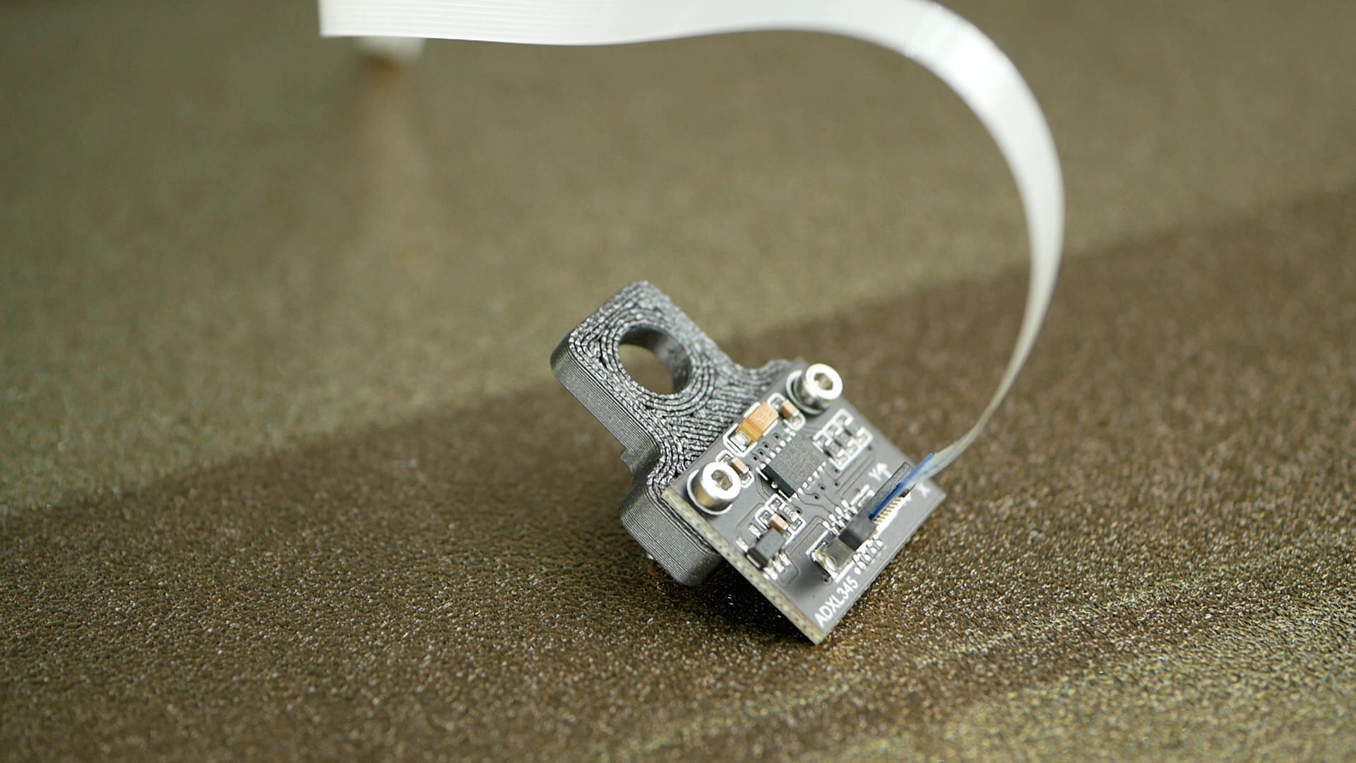
Accelerometer Board
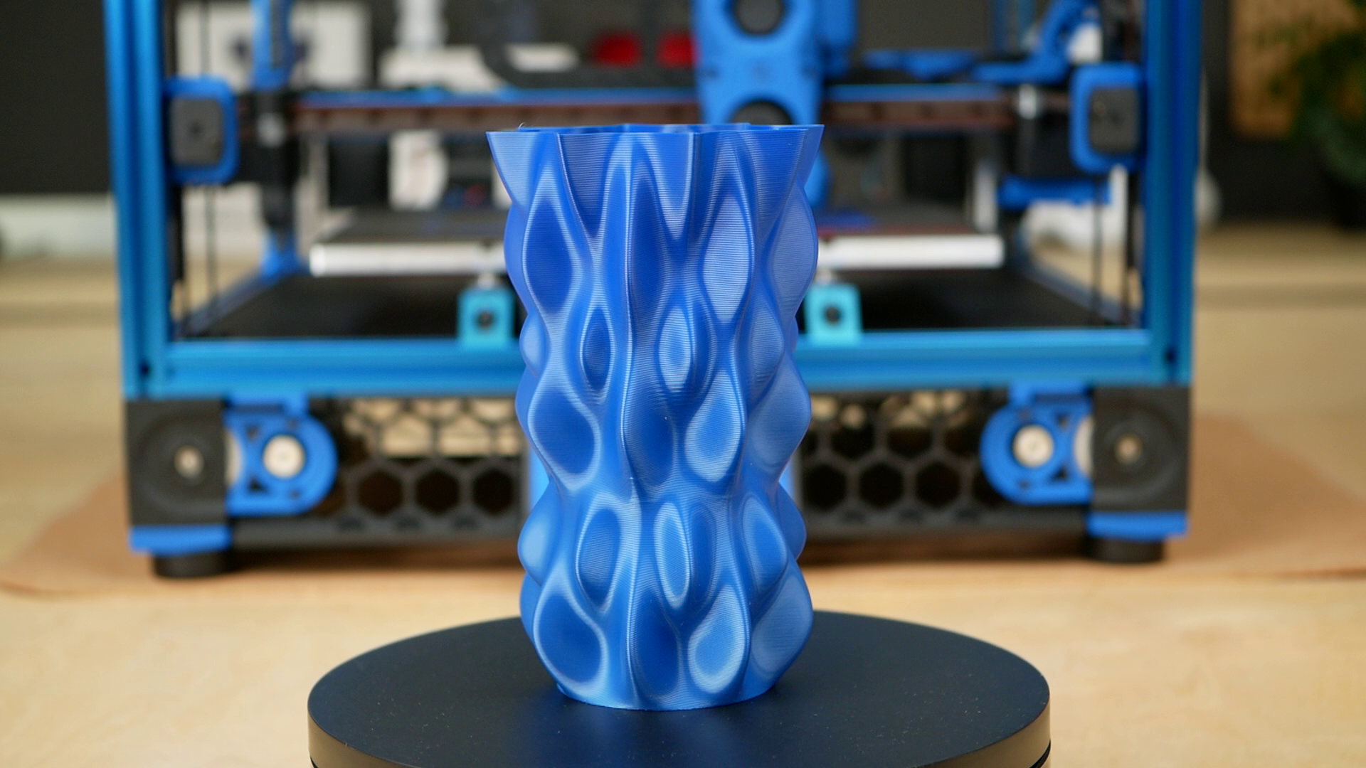
This allows for faster printing due to higher possible acceleration yet with less artefacts and less of a chance of skipped steps in the motors. I haven’t taken this to the limit yet, but even now it is already able to print very nicely looking parts at speeds way above what I know from normal bed slingers. Together with the strong cooling fan of the Stealthburner tool head this allows me to easily print my parts 50 to 100% faster than on my MK3 with standard profiles which makes this machine so efficient in use! The infamous lumpy bumpy vase test, that has a ton of very short movements also wasn’t a problem for Klipper and it handled it without any stuttering.
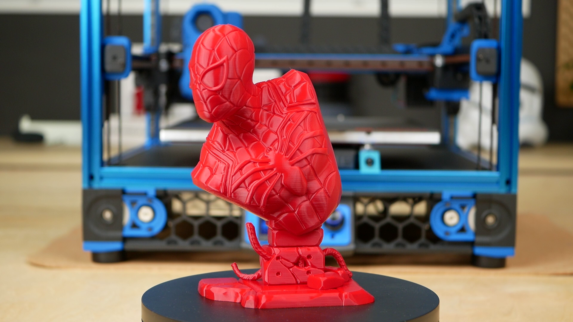
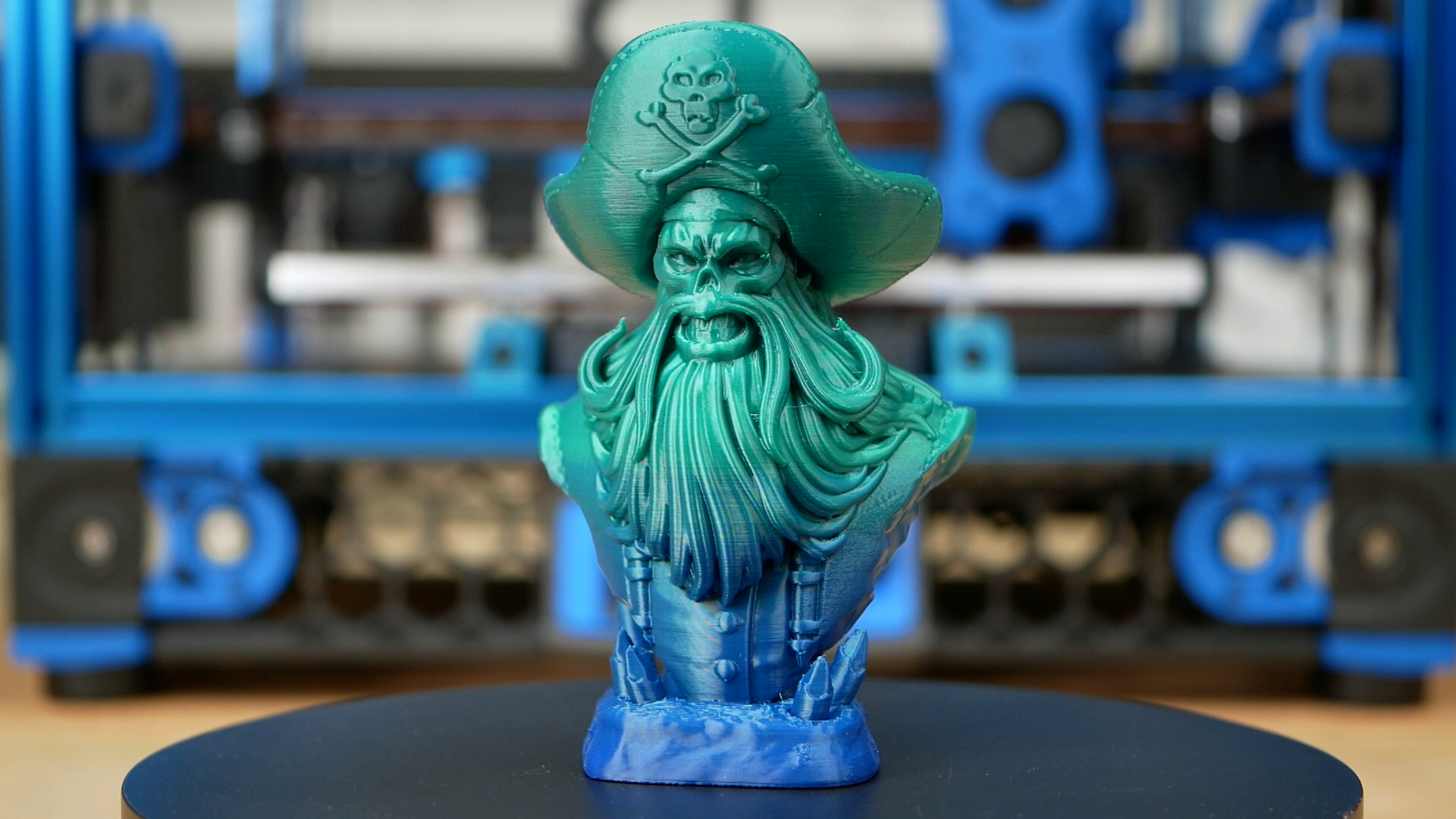
For the time I’ve been using the machine now, I can say that I’m really happy with it yet it and also the LDO kit aren’t without some minor things I have to critique. The performance so far was great. I had barely any failures and the quality of the parts is without a ton of tuning in materials and profiles really good. The mechanical design of the printerll is rock-solid, sometimes might even looks over-engineered but in the end, is exactly what you expect on a machine that will set you back a good $1500! Quad gantry leveling will make sure the gantry is always perfectly aligned to the bed. Each of the belts can be nicely adjusted for the proper tension and the linear rails make everything super rigid. There are some things I still miss or where I still struggled with. The Voron 2.4 has everything yet misses a filament runout sensor in its standard configuration, which I would like to see with such a large build volume. When I printed my Stormtooper helmet I wasn’t sure if I missed a couple of grams of material on the spool and a sensor would have given me more confidence here. In the end it wasn’t a problem, because the print failed before it finished, because the standard LDO config limits the z-axis to 260 mm, whereas many shops advertise it to be 300 mm. I could squeeze out maybe 20 mm more but 300 mm total is tough. Then there is the nozzle sensor. The Voron 2.4 measures the nozzle length before each print to compensate for thermal expansion. This is a great idea, yet I still had to slightly adjust the z-offset regularly, probably because oozing filament messed up the measurement. There are easy ways around that problem like a cleaning station, yet this annoyed me a little. Then there were some minor things I struggled with on the LDO kit. My LED and one fan wire was a bit too short. One grubscrew of a Bondtech gear was missing and I had to grind down another one, which was a pain, yet there were plenty of spares for the rest of the fasteners that you don’t need to worry if you lose one. But I think the most serious problem was that I had a ton and in my opinion too much drag in the reverse Bowden tube that was included by LDO. I’m not sure, if it was the material, or a kink in the hose, but this could cause serious headaches for some and I replaced it right away when I noticed it. Since noise is something I also critique on many other machines, I’ll also do it here. My Voron 2.4 is not a quiet printer, far away from a MK3 for example. The fans are quite noticeable because they are rather beefy and in my configuration, all the stepper motors aren’t quite as well to give them the proper torque for reliable operation. This is a critique on a high level and something most won’t care about on such an industrial machine. Everything else was great and you could notice LDO tried to get feedback from the Voron team to create a kit that met the quality standards of Voron. I can seriously recommend this kit because it will make the process of building a Voron way more enjoyable as it was in the past!
Maximum z-height limited by drag chain
Yet the question that remains is if you should still go through the hassle of building a Voron and spend more than $1500 in a time where you can buy machines like the Bambulab X1 for even less than that which comes fully built and working out of the box and might to a certain degree even allow you to print faster. So is the hype around Voron real? In a way, I think yes. The machine is so well designed and built that this can be a reliable workhorse printing almost any material you throw at it and if you do the necessary tuning it will also be able to print significantly faster than other regular machines at a noticeably better quality. Still, I think some of the hype comes due to the fact that owning a Voron wasn’t that easy, because it required dedication and skill to build one. So anyone who had a Voron was in kind of an elite club and everyone who hadn’t one desired to be in that club which definitely fuled the hype. But let’s see how the easier availability due to nice kits like the LDO one and who knows, maybe even pre-built machines will do to that hype. Excuse the comparison right here, but in a way the hype and community involvement around the Voron is a bit similar to the Ender-3s. Of course, they are in a way different price category and do have way different capabilities right out of the box. Yet, both fule this community involvement with mods and customization options which is part of the hype. People build their machines, know every scratch, kink, and setting optimization and therefore develop a kind of bond to the printer.

Bambulab X1
And here comes the Bambulab X1, which is beside the smaller print volume a probably almost as capable machine, but in a way a boring machine. You don’t assemble it, you are supposed to use their slicer and you can’t really mod it. So it lacks all of the joy of tinkering with a machine but I don’t say that’s a bad thing, because many might not enjoy that and need a printer as a tool and not a project. And this is what the Bambulab is and what probably also Prusas upcoming XL will be. Good tools, yet a bit boring. So there are different target audiences - if you want to build YOUR machine, if you want full control over it in terms of spare parts, configuration, software and whatnot yet still own a very capable tool, seriously consider a VORON or also similar kit machines like a Ratrig! It has never been easier to get one. Yet, if you are only looking for a tool, and can’t afford to spend 50, 100 or even more hours to build and tune it, take a look at capable pre-builts like the Bambulab X1 or others that suit your wallet and application.
Get an LDO Voron 2.4R2 Kit
Matterhackers (US): https://geni.us/AtBg1QM
3DJake (EU): https://geni.us/vt1m
Worldwide Resellers: https://docs.ldomotors.com/voron/LDO_Voron_Distributors
Get an LDO Voron 0.1 Kit
Matterhackers (US): https://geni.us/AKABg
3DJake (EU+): https://geni.us/fNO0q