DIY High Flow 3D Printing Nozzle
I recently showed you how with Bondtechs CHT nozzle you could almost print three times faster because it can melt filament way more efficiently by splitting it into three strands. The fundamental problem of heating a 3D printing filament is that the polymer conducts heat very slowly. If you print fast, the material is not yet properly heated through before it reaches the nozzle tip. By splitting the material up, you decrease the distance from the heating surface to the center of the material, thus melting it more quickly. Bondtech licensed the core heating technology from 3D Solex for their design and uses a quite sophisticated machining approach to generate the shape. When looking at the patent, you can also see other approaches to heat the filament not only from the outside but also from the inside. One is a simple bar that's perpendicular to the flow direction. Hard to manufacture conventionally, but what happens if we simply stick a piece of wire through a standard nozzle? This is exactly what I did.
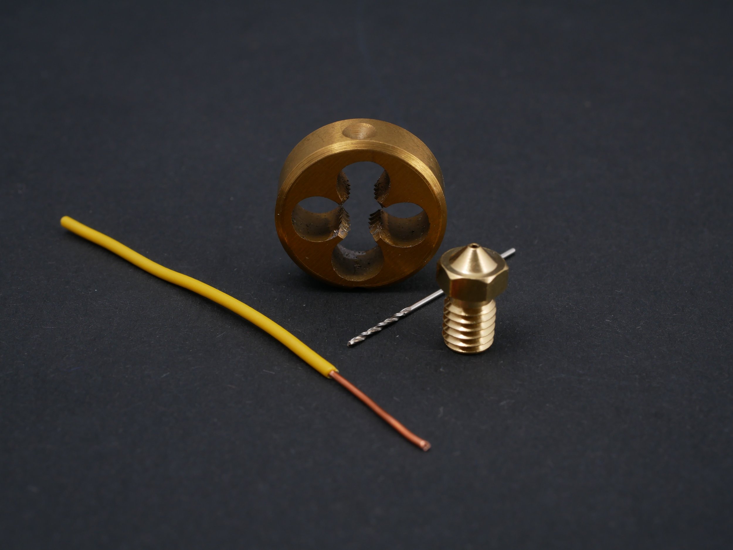
Materials used to make a DIY High-Flow Nozzle
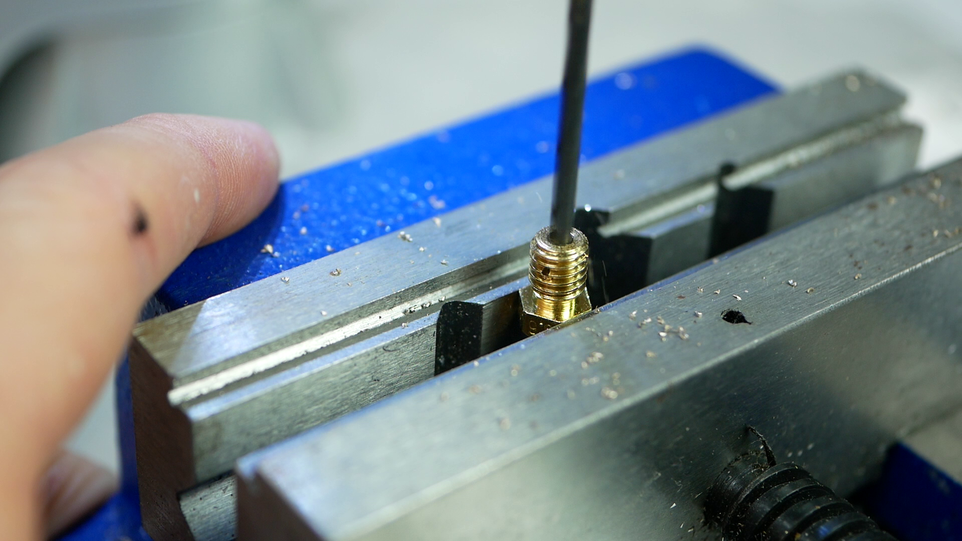
I used a standard 0.6 mm V6 nozzle, a piece of 0.8 mm copper wire, a 0.8 mm drill bit, and an M6 threading die. I first drilled a 0.8 mm hole 1.5 mm from the beginning of the threads. For that, I fixed the nozzle in a vice and looked for an orientation where I could drill between two threads. Working with these tiny drill bits isn't that easy, and I even had to change the chuck in my drill press so that I was even able to mount the bit. During my investigations, I drilled quite a bunch of nozzles but due to my crude setup was never able to hit the center perfectly because the drill always wandered off. I'm sure proper machinists can tell me how to do a better job.

Drilling the hole
Then I used a piece of telephone wire that incidentally also just had a diameter of around 0.8 mm and threaded it through the hole. Now I preheated the nozzle with my hot air station and soldered the wire to the nozzle. This can be tricky because the nozzle sinks quite some heat, so it takes a while until the solder properly flows! I made sure to use lead-free solder that has a melting point of 227°C. I'm lucky that I checked before I started because my usual leaded electronics solder already melts at just slightly above 180°C, which isn't suitable for our printing temperatures. Ideally, you should use something with even a higher melting point like silver solder, but that would substantially increase the efforts.

Soldering the wires
Of course, we can't use the nozzle like this because the threads are blocked. That's why I snipped off the ends of the wire and used a simple M6 die to recut the threads. The copper and solder are so soft that I could easily do this with my fingers, also making finding the beginning of the existing threads way easier. And there we have it - my DIY high-flow nozzle. I call it the Mesh Nozzle.

Re-cutting the threads with a die
Though let's quickly talk about the elephant in the room, and this is the patent. Yes, I'm pretty sure that if I sold this DIY high flow nozzle, I would infringe on the 3DSolex patent. Luckily here in Germany, you can recreate a patented invention if it’s purely for private and non-commercial use. In the US, even this is prohibited if there's a US patent! Making a video about something patented and earning ad revenue might be a bit in the grey area, so I just contacted 3DSolex right after my CHT video and had a lovely call with the owner of 3DSolex and the inventor and patent holder of the Core Heating Technology. Carl is a super nice guy and also shares a great passion for 3D printing which you can also see in his products like the high flow and abrasive print cores for Ultimakers with swappable nozzles. If you ever worked with Ultimakers you’ll understand my enthusiasm. Anyways – Carl gave me the blessing to play around with the things mentioned in the patent and present the results to you.

Core Heating Patent
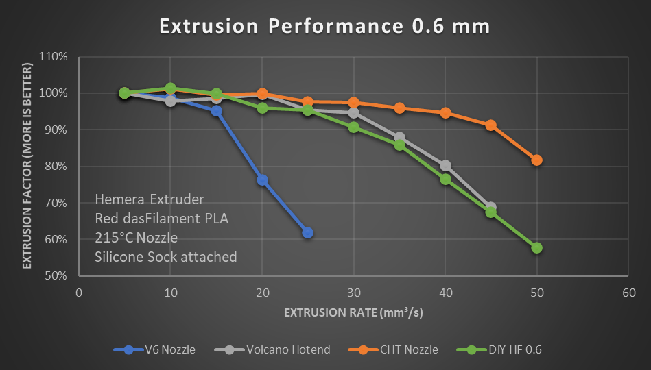
Let’s benchmark the DIY high flow nozzle! We'll look at two different performance factors this time because I noticed that a high possible extrusion rate doesn't necessarily mean that you can also print well at these rates. The first benchmark is the classical extrusion test, where I simply tell the extruder to feed 200 mm of filament through the nozzle at different speeds. The faster we go, the more backpressure we will have, which causes some slipping at the extruder gears and, therefore, less material that comes out of the nozzle, which I can simply measure with a precision scale. I did all tests on my E3D Toolchanger with a Hemera extruder, silicone socks over the heater blocks while using standard PLA at 215°C hotend temperature.

Extrusion Test
To have some reference to compare the DIY version to, let's first test a standard 0.6 mm nozzle without any modifications. 5 and 10 mm³/s still worked well, and at 15 mm³/s, we under extrude a reasonable 5%. Anything more than that is not really possible, and the plot drops way down. Next comes the typical upgrade you usually get when you want to print faster or with bigger nozzles– a Volcano hotend. Due to its longer hotend and meltzone, the filament has twice the time to melt, allowing you to extrude more material. The Volcano hotend with the 0.6 mm nozzle performed well all the way up to 30 mm³/s until it significantly dropped. This is also well visible on the extruded material because starting at 35 mm³/s, you can clearly see melt inconsistencies. The current king, the CHT nozzle is even a bit better and shows a superb performance until 40 mm³/s and only then drops off.
Let's now get to the DIY high flow nozzle. It performed well at 5, 10, 15 and even 20 mm³/s, so it at least outperformed a regular nozzle. Even at 25 mm³/s, there isn't any real performance drop visible. After that, we see the performance gradually decreasing, interestingly in a very similar manner as we've seen with a volcano hotend, which is pretty impressive!
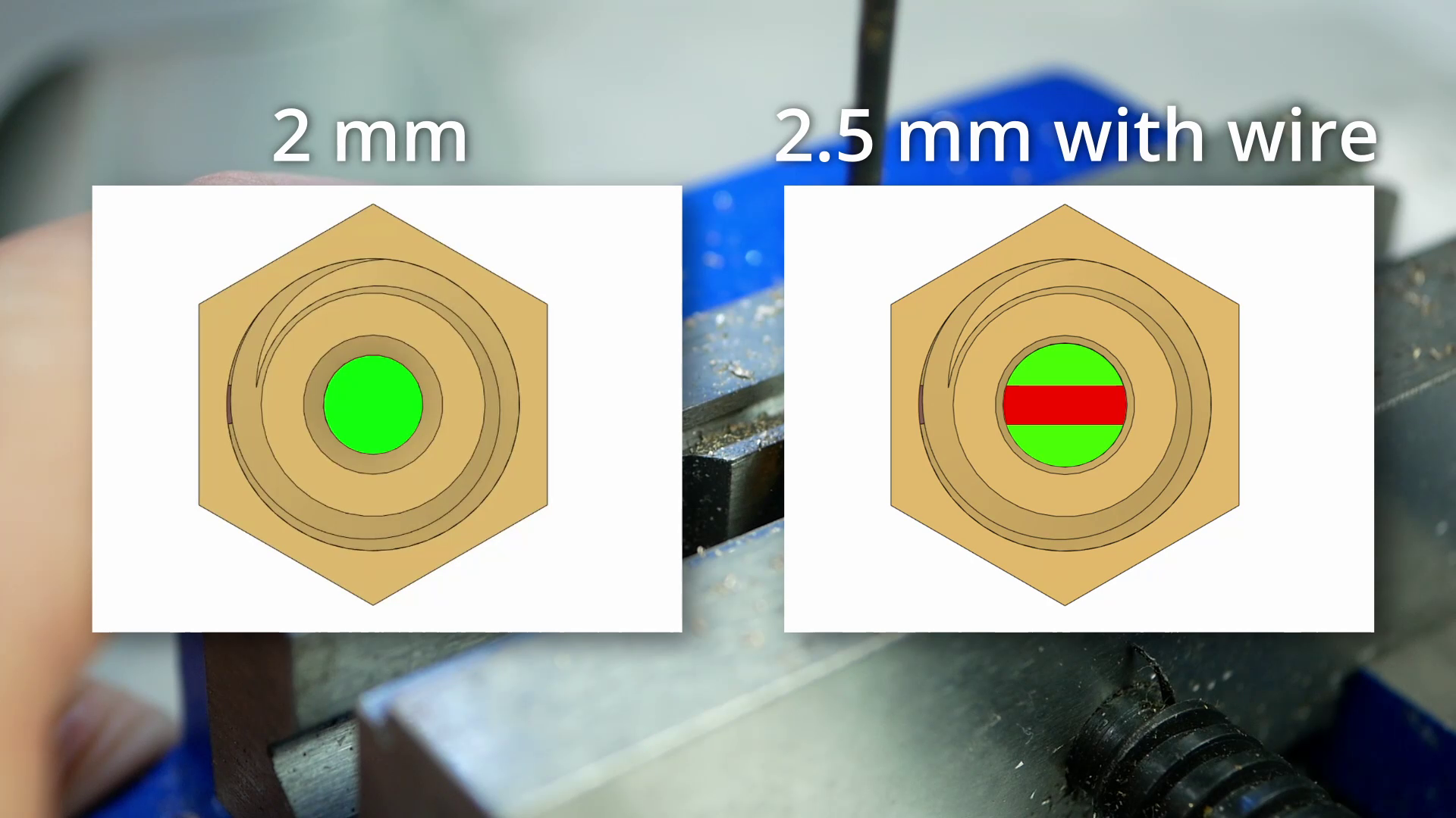
But let's take a look at the geometry of our DIY high flow nozzle. Adding the piece of wire significantly decreases the hole area within the nozzle. This means that even though the wire is helping with the melt rate, the added resistance again decreases the flow. I tried to get around this by increasing the bore size where the wire is from 2 to 2.5 mm, so that the resulting surface is similar to the unobstructed one. This adds an undercut at the transition to the heatbreak but from my previous tests with Bondtechs CHT and print tests with this one, it doesn't really impact retraction performance. I was even able to clean the nozzle with a cold pull!
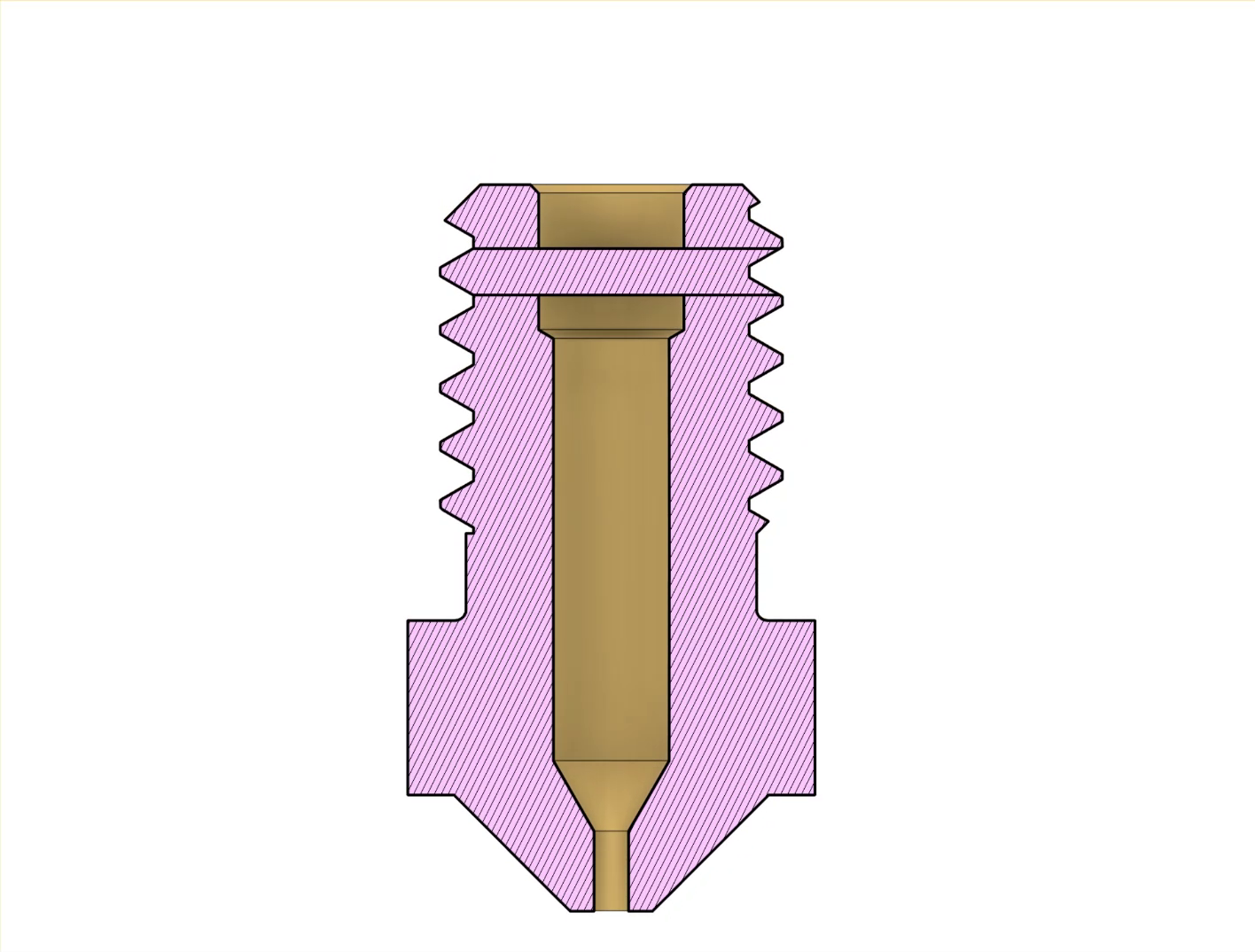
Testing this design showed that this really significantly helped, and the drilled DIY high flow nozzle performed great up to 35 mm³/s and only then dropped off. It didn't beat the CHT yet, though I'm really getting close.


You may now ask yourself, if one piece of wire improves the performance that much, well, how would adding two wires perform? That's why I modified yet another nozzle by drilling two holes 90° apart from each other at 1.5 an 2.5 mm depth and again soldered wires in and finished it up with a die.
This one interestingly performed similarly to the volcano and the undrilled mesh nozzle, which shows that a second wire on the one side might help with melting. On the other side it adds additional turbulence and flow resistance which is detrimental for performance.

Just on a side note - the reason why the extrusion from the volcano stay straight and the ones from my DIY high flow curl up are the unsymmetric nature of my pin placement that cause an unsymmetric shear profile in the melt, making the material bend up in the direction of the smaller hole.

Unsymmetrical placement of the wire in the nozzle causes coiling extrusions
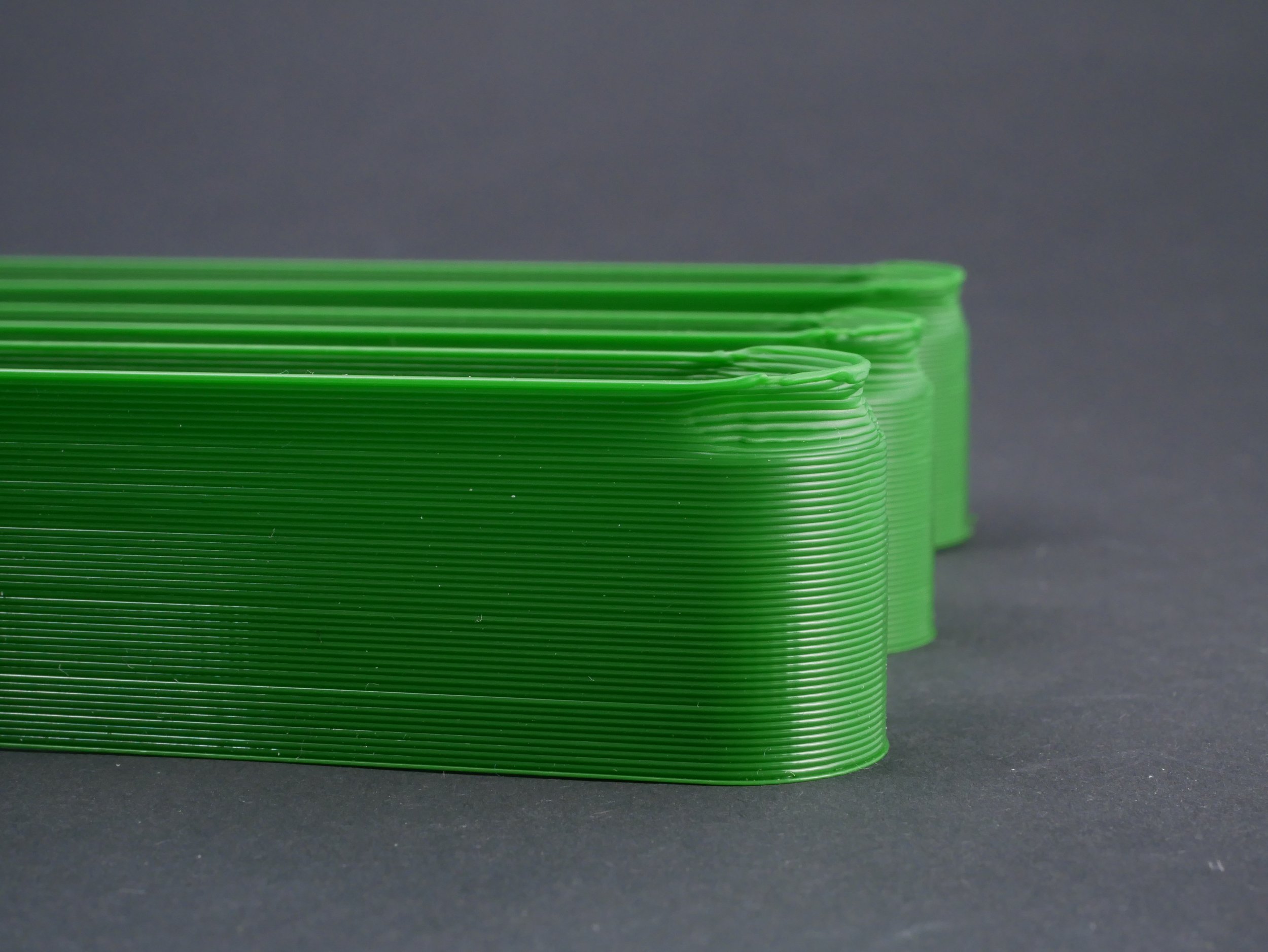
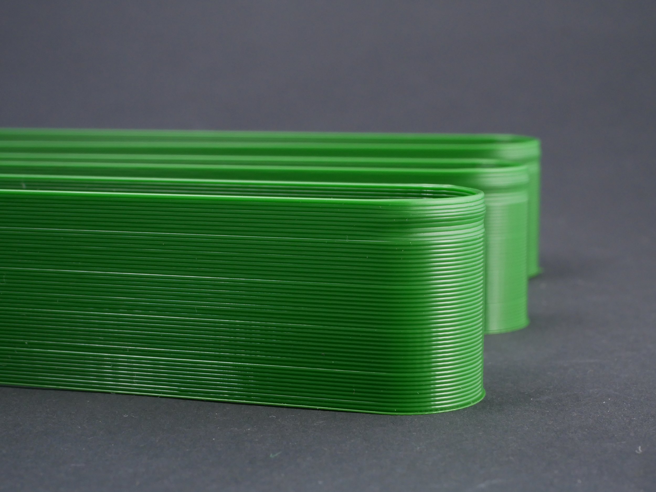
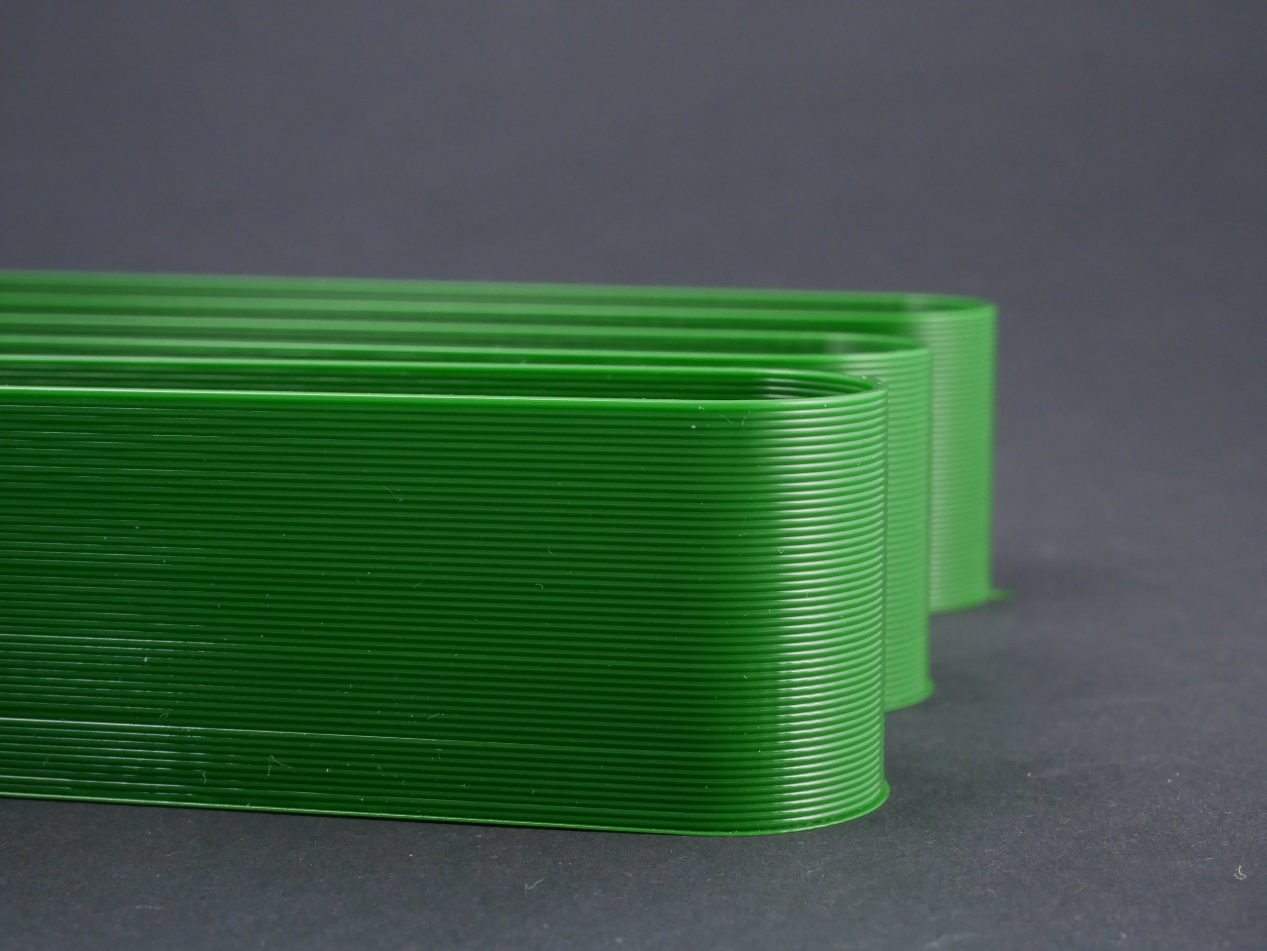
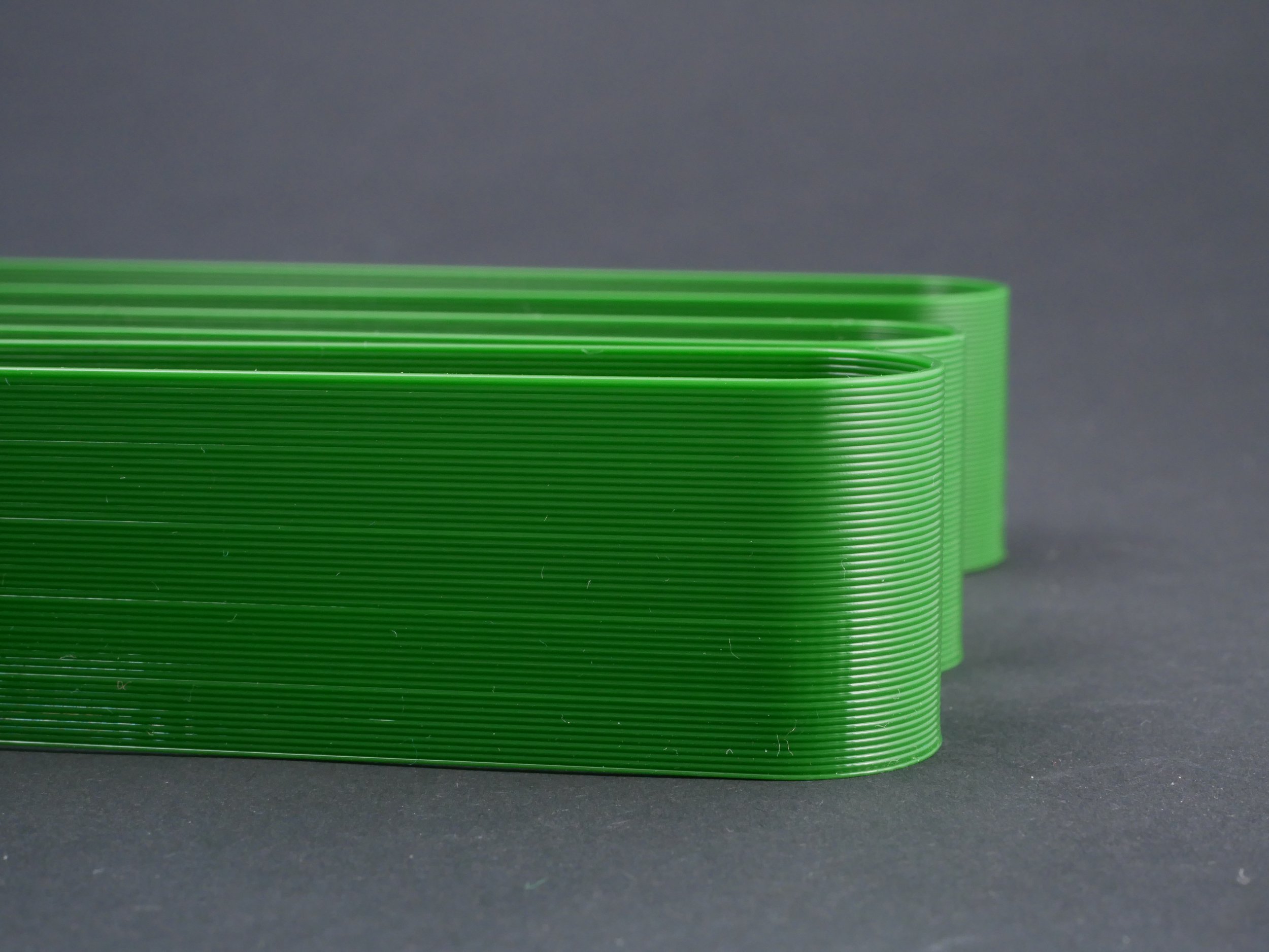
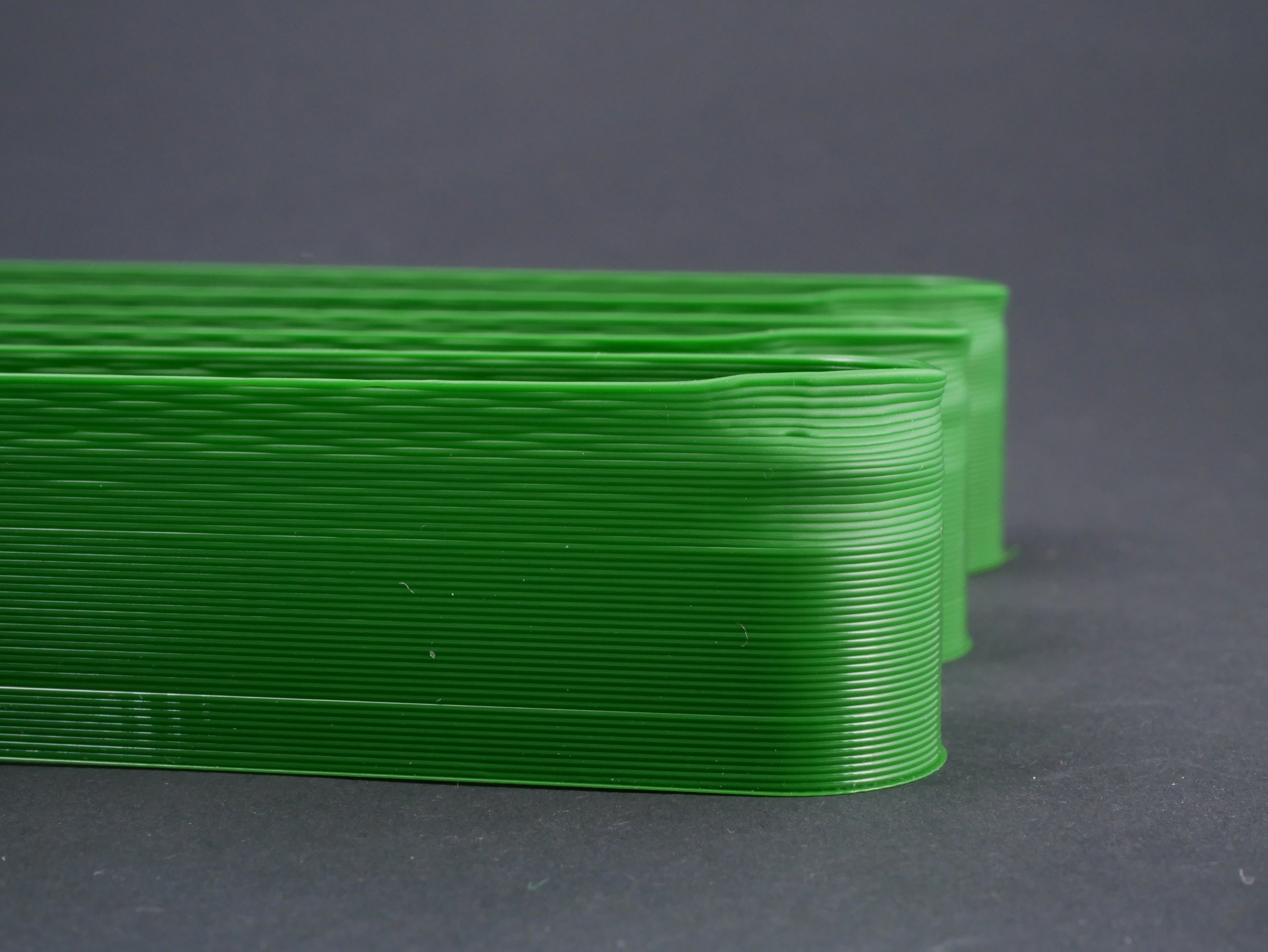
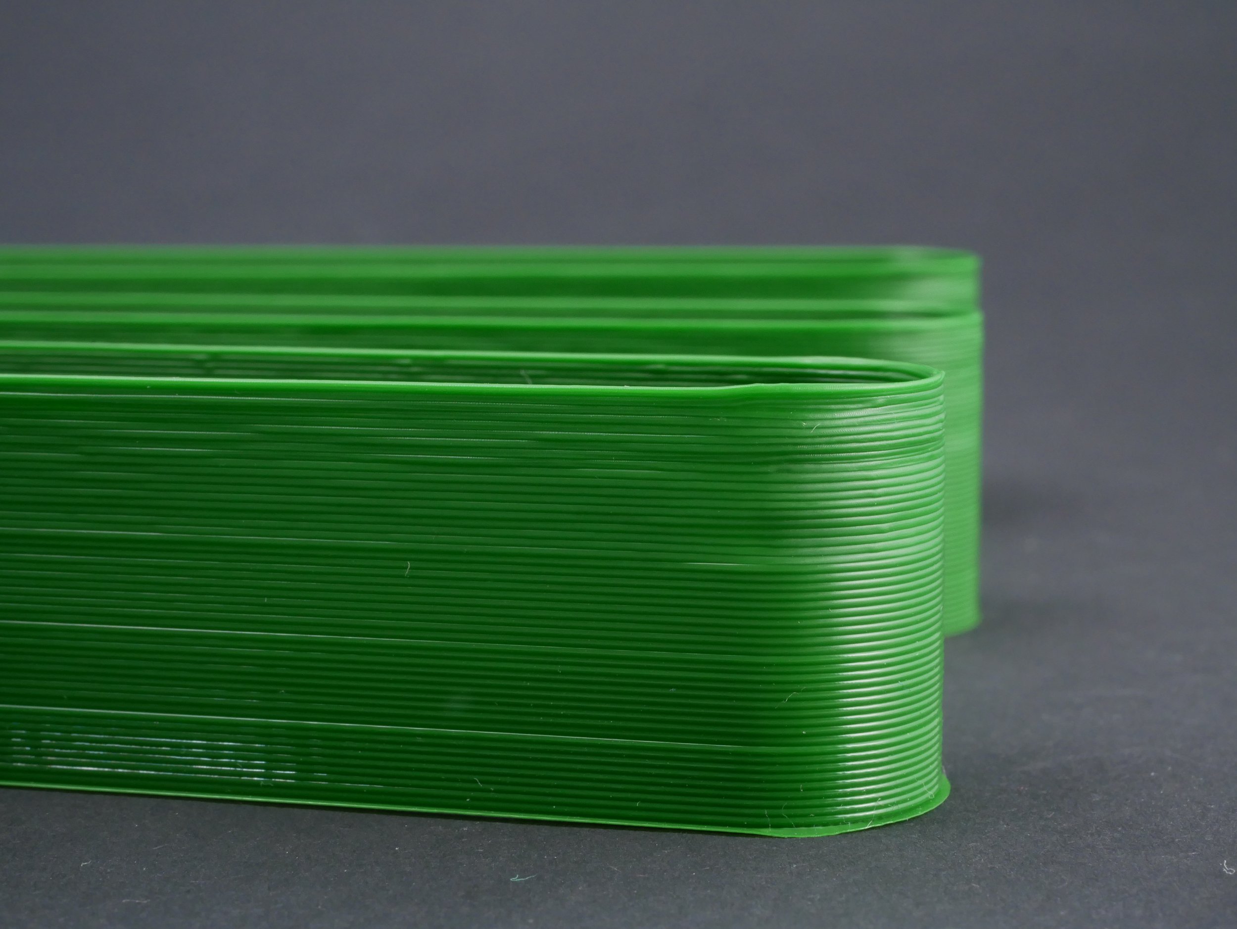
I talked about using two different tests to benchmark the performance of a nozzle and the second one might even be more important than the pure extrusion performance we just tested. If you closely watched the extrusion benchmark before, you have noticed that the filament strand significantly changed shape depending on the extrusion rate due to die swell.

Die Swell at different extrusion rates
Die swell is the phenomenon that a melted polymer partly tries to get back to its original shape before passing the nozzle, resulting from its viscoelastic nature. The lower the viscosity before the nozzle and the shorter time it has to pass through the orifice, the higher the die swell you usually have. Die swell is caused by the internal stresses caused during compression that try to release again. Suppose this prestressed material is printed and therefore basically pinned on an existing layer. In that case, these internal stresses remain in the material and can cause printing problems like warping or curling on overhangs.
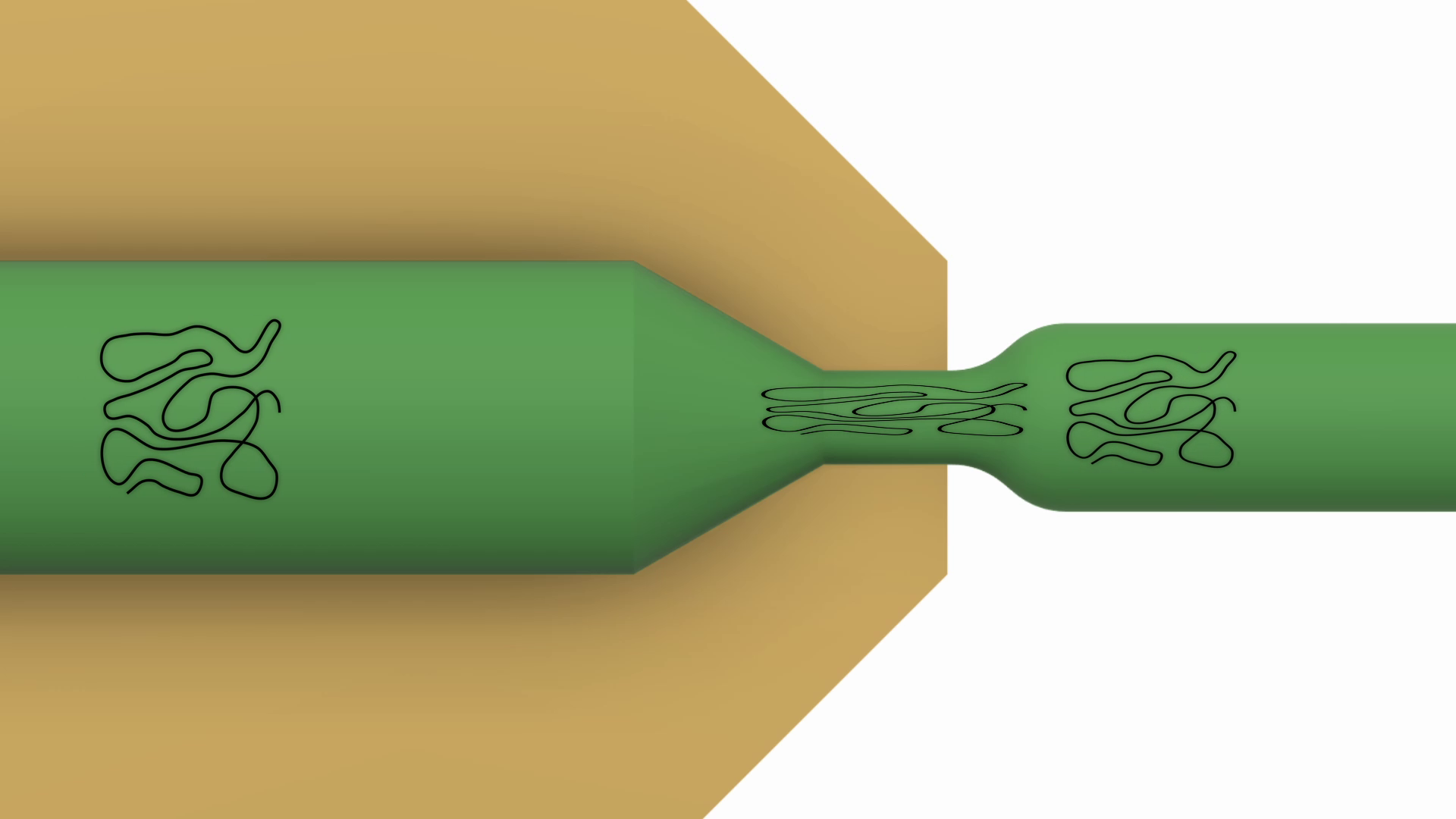
Compressed and relaxed polymer chains cause dies swell
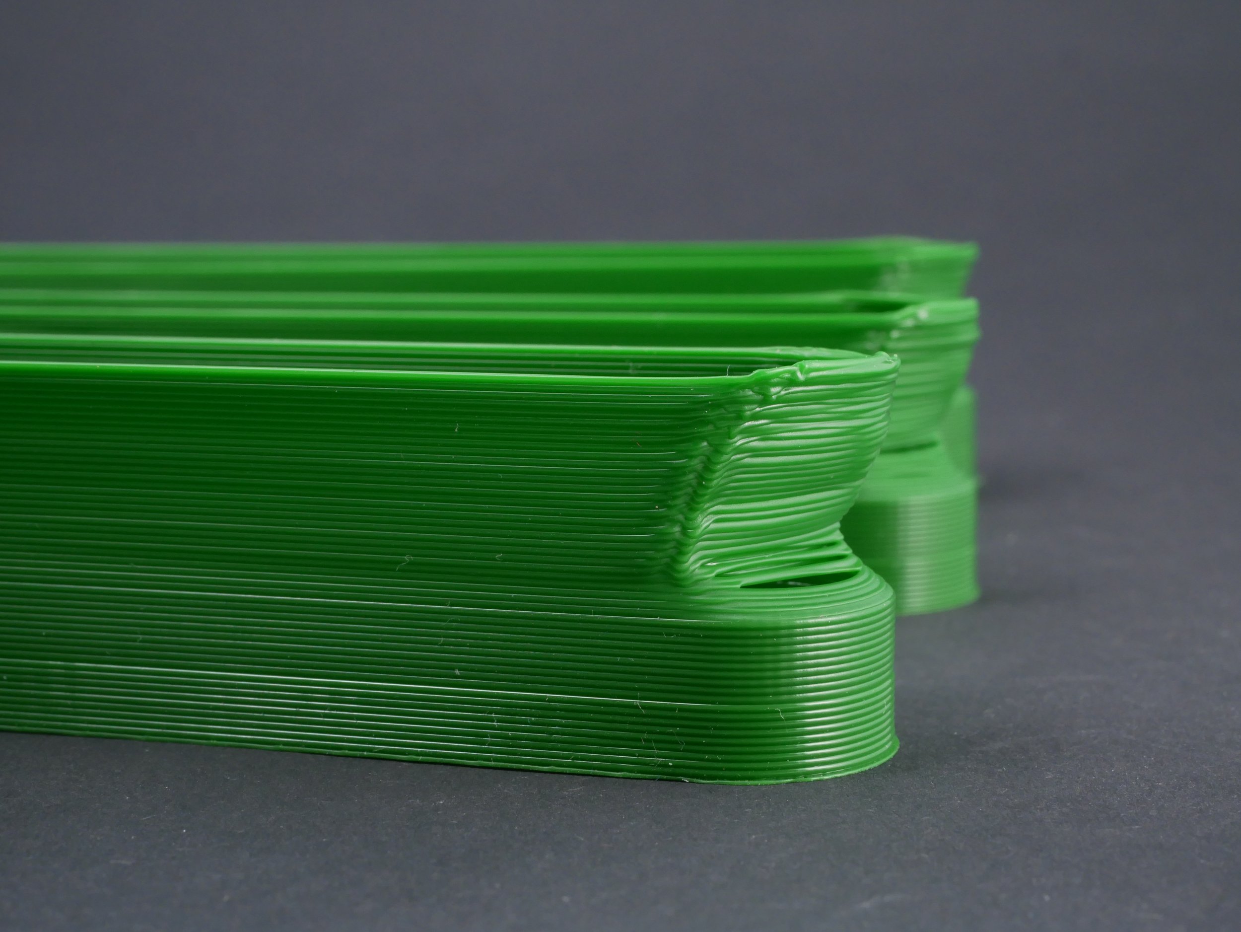
To test printing performance and residual stress I designed a meandering part that I print in vase mode at increasing extrusion rates by simply increasing the speed factor every 5 mm starting from 10 all the way to 30 mm³/s. Printing problems at specific extrusion rates can show in two different ways. Under-extrusion because the feeder is just not capable of pushing enough material causing thinner extrusions or even voids in the wall. Then there are printing problems caused by the internal stresses, especially seen at the corners. If the extrusion line is prestressed, it tries to find a state of minimum potential energy, which I can simply illustrate by a piece of pre-stressed rubber band that tries to snap back to a short line instead of the elongated curve. Of cause cooling also plays some role here because if you solidify the extrusion before it can deform, you freeze the internal stresses. Since I used the same cooling solution for all of the parts besides the volcano, the results should be very comparable though.

Extrusion Test part with Volumetric Flow Rates.
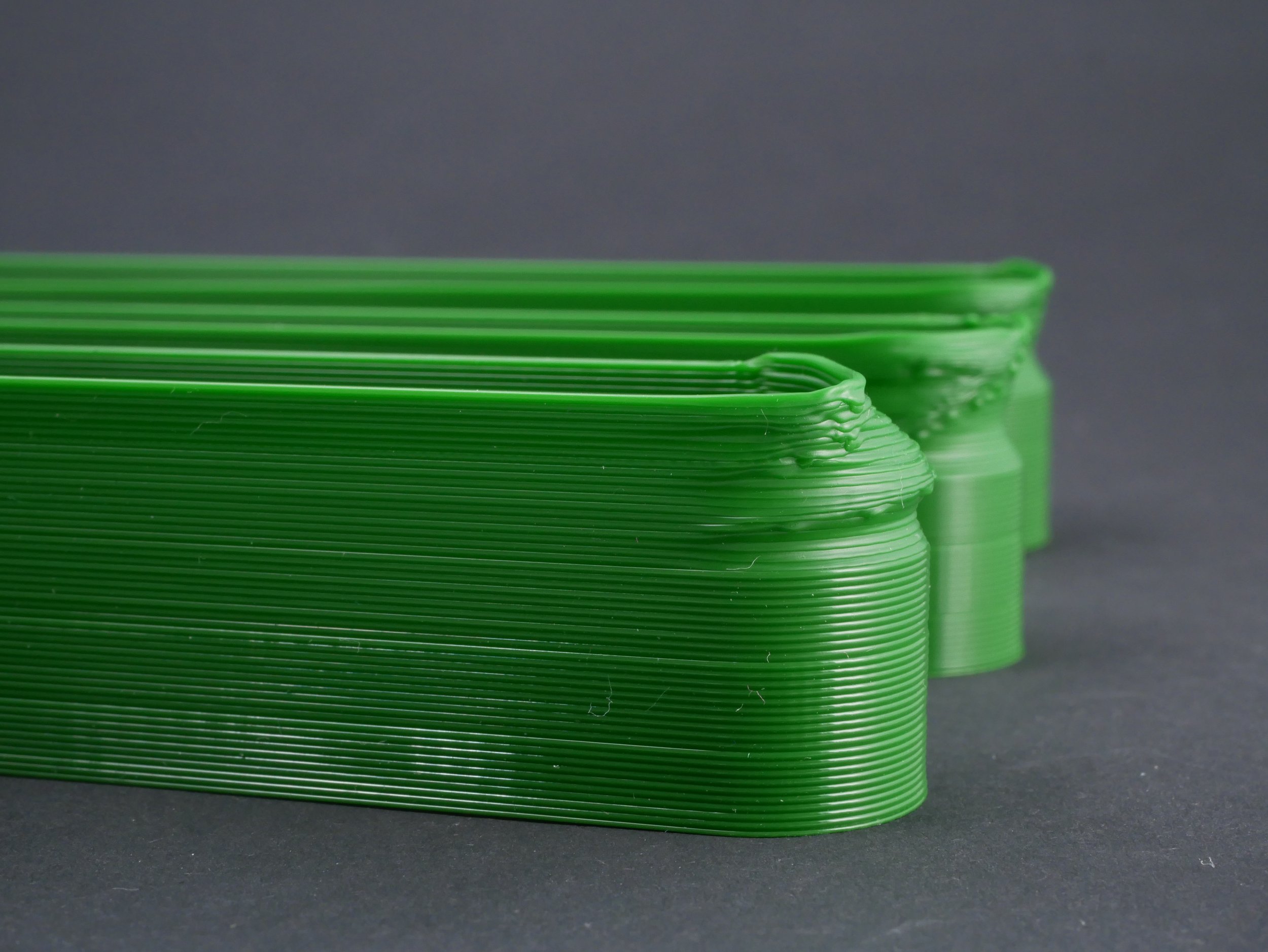
So let's rank the different nozzles. The standard 0.6 mm V6 nozzle printed 10 and 15 mm³/s well but then spectacularly failed at higher extrusion rates. This correlates well to our extrusion tests, where also at 20 mm³/s, extrusion rates plummeted. Here it goes even all the way to the point that the lines don't properly adhere anymore due to under extrusion and probably being partly unmelted. Next already comes the Volcano hotend that's good until 20 mm³/s but then failed. I wasn't able to spot significant under extrusion, but the internal stresses caused the corners to bulge in.
Interestingly, the next contestant is the DIY Mesh Nozzle that was drilled bigger and landed in second place at the extrusion tests. This probably means that enlarging the hole decreased flow resistance but somehow also decreased the melting performance because the distance from the sidewalls to the center of the material increased. Extrusion performance is a well-tuned system of flow resistance and melting performance. Both impact the amount of material you can push through a nozzle, but that doesn't mean that the extruded material ends up with the same properties. In third place comes my first DIY high flow nozzle that performed well, all the way to 25 mm³/s, and only then showed some degeneration.
So now there are only two nozzles left. The CHT nozzle and my double wire DIY high flow nozzle. Who's taking the win? Both nozzles performed similarly in this test, and on the benchmark part that goes all the way up to 30 mm³/s no differences are visible.
So, of course, I had to increase extrusion rates and up the rate by 10 mm³/s each step to end up at 50 mm³/s on the top section. Here, the CHT, unfortunately, takes the lead. Even though both show degradation in quality starting at 40 mm³/s, there is more deformation with my DIY version and even a couple of holes at 50 mm³/s. Still not bad for a first shot, or what do you think?
I think all of the investigations show the potential of different melt zone geometries for high flow extrusion systems. Even though these high flow hotends aren't really necessary for common printers using 0.4mm nozzles, I'm still excited to see what's all currently happening in this field, even from other tinkerers. I think I just scratched the iceberg with my tests because there are that much more things to investigate like different wire diameters, the number of wires, geometries, positions, orientations, and materials. Plus, the use of electronics solder limits the material choice to PLA and maybe PETG. Next, I definitely want to try the same with volcano nozzles to see how much I can improve them! Of course, much of this falls under the 3DSolex patent, so don't expect a ton of commercialization soon, but there is still the option of licensing and smartly working around that patent. My Mesh Nozzle also doesn't make the CHT nozzles obsolete due to their very competitive price but might give you the option to mod other special nozzles. Definitely let me know your ideas and thoughts down in the comments, and tell me what you'd like to see me investigate next!
Thanks to 3DSolex for making this investigation possible!
Links
3DSolex and their Ultimaker Print Cores
CHT Nozzle - V6 Compatible (Affiliate in DE/UK)
CHT Nozzle - Mk8 for Ender 3 and similar (Affiliate in DE/UK)